background image

26

Preparation for operation/Operation

Electrical diagram

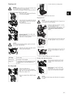
Filling water

Dosage:

Only use chemical products recommended by the manufacturer.

The dosing cap is marked for a 1% cleaning solution.
Dosing example:

Before the machine can be put into operation, you must connect 
the two parts of the machine electrically and screw the handle 
onto the body of the machine.

Use the assembly instructions on page two of these instruction of 
use.

Caution:

Maximum permissible water temperature 35 °C/95 °F.

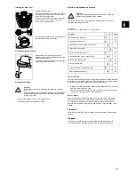
• Remove the tank from the machine by pulling 

the tank unlocking device (1).

Hold the tank (2) with your other hand (2) so that 

it cannot fall out of its bracket while being 

unlocked. Pull the water tank out of the bracket.

• Remove the dosing cover. The dosing cap can 

be removed from the filter housing by turning it 
to the left.

• Fill up the fresh water tank up to the mark.

11

10

12

14

13

15

8

6

1

2

5

3

4

9

7

Y/G

WHITE

BLACK

BLACK

BROWN

GREEN

WHITE

WHITE

WHITE

BLACK

BLACK

RED

BLUE

GREEN

RED

WHITE

BLACK

GREEN

RED

WHITE

Y/G

BLACK

BROWN

RED

11

10

12

16

16

14

13

15

8

8

1

2

5

3

4

9

7

BLACK

BROWN

Y/G

WHITE

WHITE

Y/G

Y/G

WHITE

BLACK

BLACK

RED

BLUE

GREEN

BROWN

RED

Y/G

230V / 50-60Hz
100V / 50-60Hz

120V / 60Hz

13
14
15
16

- Wires kit base
- Circuit board
- Brush motor
- Wire kit vac/base

  7
  8
  9
10
11
12

- Pressostat (for pump version)
- Pump or Electro valve
- Thermal protector pump
- Terminal block
- By-pass vacuum motor
- Microswitch

1
2
3
4
5
6

- Terminal block
- Main switch
- Vacuum switch
- Pump switch
- Wires kit electric panel
- Wires kit upper housing

WHITE

WHITE

WHITE

BLACK

GREEN

2

1

1

2

• The mark is indicated by a label on the side of 

the fresh water tank.

Caution:

Wear protective gloves, goggles and the corresponding 
(protective) work clothing when handling chemical products!

Caution:

Using other chemicals (e.g. chemicals containing chlorine or 
hydrochloric acid) can damage or destroy the machine.

Dosage

Tank capacity

Dosing aid

1%

MAX

1 x MAX

• Use the dosing cap for the dosing. The dosing 

cover can be removed from the filter housing by 
turning it to the left.

• Fill the dosing cap with cleaning water up to the 

marked level (26 ml =1%).
Empty the contents of the dosing cap into the 
fresh water tank.

• Return the dosing cap back to the opening 

provided.

Ensure that the dosing cap is turned in exactly 

as shown in the illustration. The Taski lettering 

must be at the bottom. Only in this way do the 

ribs on the dosing cap fit into the cutouts 

provided in the tank.

• Fit the filter housing onto the tank and lock it into 

place.

In doing this, ensure that the filter housing lies 

correctly on the tank. The locking device on the 

front side of the tank is designed for this. (See 

the detail in the illustration).
The tank could open by itself during cleaning.

• Replace the tank (1) in the machine again until 

it locks into place and press the tank unlocking 
device (2) into place again.

M A X

WATER      LEVEL

LIVELLO    ACQUA

WASSER   NIVEAU

NIVEAU DE L`EAU

NIVEL DE L`AGUA

Temperature

+5°C    +  +35°C
+41°F  +  +95°F

M A X

WATER      LEVEL

LIVELLO    ACQUA

WASSER   NIVEAU

NIVEAU DE L`EAU

NIVEL DE L`AGUA

Temperature

+5°C    +  +35°C
+41°F  +  +95°F

1

2

-  1% / 26ml  -

-  1% / 26ml  -

TASKI

1

2

Summary of Contents for Swingo 150

Page 1: ...swingo 150 V005 12089 59 0921 I25 I24 I23 I22 I21 I20 I19 I18 I17 I16 tr sl se pt pl no nl it fr fi es en de da cz 12089 59 ...

Page 2: ...2 Swingo 150 1 3 5 2x M6x20 7 2x CLICK 2 4 2x M6x20 6 2x ...

Page 3: ...ance Do not use this machine in rooms in which explosive or easily inflammable materials e g petrol solvent fuel oil dusts etc are stored or processed The electrical or mechanical components could cause these materials to ignite The machine must not be used in rooms subject to electromagnetic fields electrosmog Do not use this machine to vacuum toxic poisonous caustic or irritating substances e g ...

Page 4: ...lity 89 336 EWG Harmonised standards applied EN60335 1 2002 A11 2004 A1 2004 A12 2006 A2 2006 EN60335 2 2 2003 A1 2004 A2 2006 EN50336 2003 A1 2006 Through internal measures it has been ensured that series production units conform to the requirements of current EU Directives and relevant standards at all times The signatories act on behalf of company management and with full power of attorney Over...

Page 5: ...acuum switch Pump switch Wires kit electric panel Wires kit upper housing WHITE WHITE WHITE BLACK GREEN 2 1 1 2 The mark is indicated by a label on the side of the fresh water tank Caution Wear protective gloves goggles and the corresponding protective work clothing when handling chemical products Caution Using other chemicals e g chemicals containing chlorine or hydrochloric acid can damage or de...

Page 6: ...ton to the right for more or to the left for less brush pressure Switch off the water pump 1 Allow the suction unit to run for 10 seconds more so that the remaining water will be sucked out Switch off the suction unit 2 Switch the machine off main ON OFF switch plug 1 2 1 2 MAX BRUSH PRESSURE MIN RED GREEN 1 2 Lock the machine in the vertical position Wind the mains cord around the cable hooks Cau...

Page 7: ...clips to the left to release the squeegees Bring the machine onto its side to remove the squeegees x 2 1 1 2 Wash out the squeegees under running water Check the condition of the suction lips before installing Bristles that are too short or damaged suction lips could impair the cleaning result Replace the squeegees in the squeegee body In doing this note that the front and rear squeegees are diffe...

Page 8: ...body The ribs on the carrier on the brush roller must be inserted into the correct cut outs on the carrier on the squeegee body Refit the brush holder and turn it clockwise until the rotation lock latches into place Always clean the running surfaces of the transport wheels with a damp cloth before and after using the machine The transport wheels could become dirty when being transported over aspha...

Page 9: ...on Place the machine in the working position 27 The motor turns but not the brush Drive defective Call your service partner Poor vacuum performance Motor protection filter dirty Clean or replace the motor ptotection filter 27 Suction hose not con nected Check Name swingo 150 typ CO150 5 CO150 5C Rated voltage 230V 120V DC Frequency 50 60 Hz Rated power 1100 1100 W Machine weight 12 7 12 7 kg Dimen...

Page 10: ...PS Postfach CH 9542 Münchwilen Telefon 41 71 969 27 27 Fax 41 71 969 22 53 JohnsonDiversey TASKI swingo 150 E Type Serie 7516209 150 E EURO CO150 X 01 7516210 150 E SEV CO150 X 01 7516211 150 E UK CO150 X 01 7516212 150 E CSA CO150 X 01 7516674 150 E CHINA CO150 X 01 7516675 150 E JAP CO150 X 01 7516676 150 E AUS CO150 X 01 ...

Page 11: ...der No Model Stck Piè Qty Bezeichnung Designation Description 1 S007113 1 00 Griff Poignée Handle 2 S007114 1 00 Saugaggregat Agrégat d aspiration Vacuum unit 3 S007115 1 00 Tank Pumpe Réservoir Pompe Tank Pump 4 S007116 1 00 Bürstenantrieb Entraînement de brosse Brush drive 5 S007117 1 00 Elektroschema Schéma électrique Electrical diagram ...

Page 12: ... Schr KS Z 2 9x16 Vis à tôle tête cyl Bz2 9x16 Pan Head Tapp Screw Bz 2 9x16 111 3303 419 4128398 1 00 Kabelanschluss Deckel Barrete de fixation Couvercle Bearing Rail Cover 112 1854 22 4080720 1 00 L Bl Schr KS Sp 3 9x16 Vis à tôle tête cyl C 3 9x16 Pan Head Tapp Screw C 3 9x16 113 3303 420 4128399 1 00 Wasserpumpenschalter Pompe à eau Interrupteur Water Pump Switch 114 3303 421 4128400 1 00 Saug...

Page 13: ...S007113 3 TASKI swingo 150E 104 01 swingo 150 E 1 0 111 103 102 106 107 109 110 112 105 108 101 113 114 115 116 117 118 119 120 123 121 122 124 130 131 ...

Page 14: ... Schr LK KS KA40x10 Vis pour plastique KA 40x10 Screw For Plastic KA 40x10 123 4016 202 4047420 2 00 Klemmenleiste 2 Pol 2 5 mm Serre fils 2 pôles Connection Bloc 2 Ways 124 1840 020 4114420 1 00 PT Schr LK KS KA40x35 Vis pour plastique KA 40x35 Screw For Pastic KA 40x35 125 3303 439 4128419 1 00 Wasserventildeckel Couvercle Cover 126 1840 011 4079480 4 00 PT Schr LK KS KA35x20 Vis pour plastique ...

Page 15: ...wingo 150E 101 02 swingo 150 E 1 1 102 117 104 105 106 140 107 108 111 109 110 111 113 114 118 111 116 123 105 106 111 125 126 127 128 129 130 126 132 133 134 135 136 Gr 03 P 105 120 121 111 103 142 141 131 124 143 144 ...

Page 16: ...9 4128696 1 00 Wasserfilterdeckel Couvercle Eau Filtre Water Filter Cover 107 3303 452 4128432 1 00 Pumpenhalter Fixation de pompe Pump Holder 108 8881 100 4055370 0 73 Schlauch 4 7 Silikon Tuyau d silicone 4 7 le m Silicone Hose 4 7 Per M 109 3303 453 4128433 1 00 Filtergehäuse Komplett Bâti de filtre compl Filter Housing Compl 110 3303 483 4128492 1 00 Wasserfilter Eau Filtre Water Filter 111 33...

Page 17: ...S007115 7 TASKI swingo 150E 101 03 swingo 150 E 1 1 102 103 104 107 108 109 110 112 114 Gr 02 P 117 Gr 02 P 114 111 115 113 106 105 116 ...

Page 18: ...67 4128455 1 00 Stützrolle Roulette Wheel 118 3303 468 4128456 1 00 Stützrollenbügel Roulette Etrier Wheel Bracket 119 1752 35 4007480 1 00 Unterlagscheibe 4 3 12x1 Rondelle 4 3 12 Washer 4 3 12 120 1840 052 4122655 3 00 Delta PT Schr LK As Torx 50x16 Vis Delta PT Torx 50x16 Screw Delta PT Torx 50x16 121 3303 469 4128457 2 00 Halter Fixation Bracket 122 3303 477 4128465 1 00 Fusspedal Komplett Pie...

Page 19: ... TASKI swingo 150E 101 04 swingo 150 E 1 1 Gr 02 P 101 102 104 103 106 107 105 108 114 113 112 111 110 106 109 115 116 117 118 120 121 119 122 123 124 125 126 127 128 129 140 133 131 132 130 134 135 141 142 143 ...

Page 20: ...10 TASKI swingo 150E S007117 Elektroschema Schéma électrique Electrical diagram Pos No Artikelnr Article No Item No Bestellnr No de com Order No Model Stck Piè Qty Bezeichnung Designation Description ...

Page 21: ... board Brush motor LindWash 30 38 WIRING DIAGRAM V 120 60 Class I 1 2 3 4 5 6 7 8 9 10 11 12 13 14 15 Terminal block Main switch Vacuum switch Pump switch Wires kit electric panel Wires kit upper housing Pressostat for pump version Pump or Electro valve Thermal protector pump Terminal block By pass vacuum motor Microswitch Wires kit base Circuit board Brush motor WHITE Y G BLACK RED BLUE GREEN BRO...

Reviews: