
GTS
Technical Manual
26. March 2013
Edition: V2.00/2013
5-9
Copyright © 2013, Diversey Inc.
05
.1
0.2
0 ha
ndle - ha
ndle adj
ust
m
en
t lever
- 35
0B_
V1.0
0.
fm
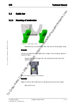
5.1
Handle
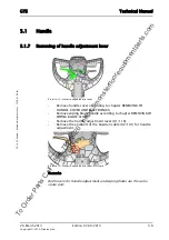
5.1.8
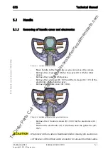
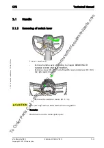
Mounting of handle adjustment lever
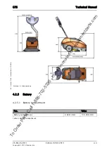
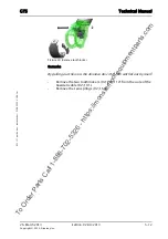
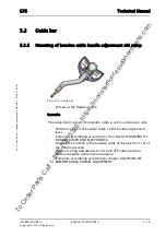
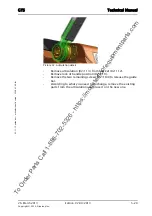
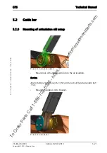
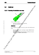
Picture 15: Handle adjustment lever
•
Mount the end bolt of the bowden cable for the handle
adjustment.
•
Mount handle adjustment lever onto handle.
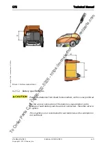
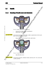
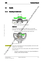
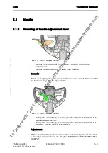
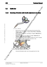
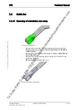
Remarks
When exchanging the lever, ensure that you also mount the lever (01/
103) for floating handle adjustment.
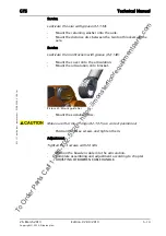
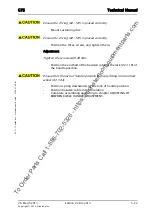
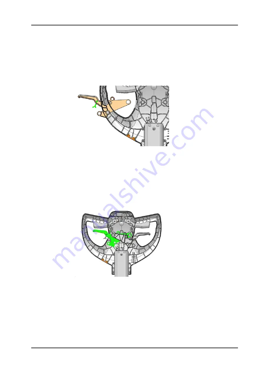
Picture 16: Handle adjustment lever
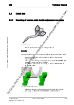
•
Complete assembling according to the chapter MOUNTING OF
WIPING BLADE LEVER.
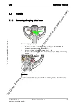
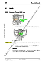
•
Complete assembling according to the chapter MOUNTING OF
HANDLE COVER AND ELECTRONICS.
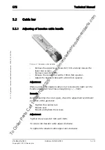
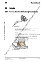
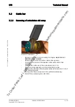
Adjustment
Make sure that the bowden cable is adjusted correctly. For the bowden
cable adjustment refer to the chapter ADJUSTING OF BOWDEN CABLE
HANDLE.
To Order Parts Call 1-888-702-5326 - https://monsterfloorequipmentparts.com


