


GTS
Technical Manual
5. March 2013
Edition: V1.10/2013
6-10
Copyright © 2013, Diversey Inc.
06.
18.
11 elec
tro
ni
cs
- 455
B_
V1
.00
.fm
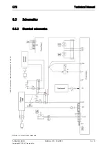
6.3
Electronics
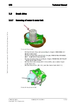
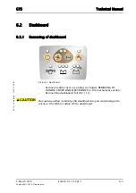
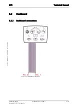
6.3.2
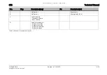
Mounting of electronics
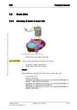
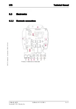
Picture 6: Electronics
•
Connect the wires to the electronics.
•
Complete assembling according to the chapter MOUNTING OF
HANDLE COVER AND ELECTRONICS.
Tighten the connectors with the correct torque. Refer to adjustment
or the spare parts list.
Adjustment
M5 screw: 5.0Nm --> +24VDC, brush and vacuum motor
M3 screw: 3.0Nm --> GND
Summary of Contents for swingo 455B
Page 1: ...Edition V1 10 2013 Technical Manual...
Page 5: ...5 March 2013 Edition V1 10 2013 Copyright 2013 Diversey Inc Technical Manual 1 Forward...
Page 8: ...5 March 2013 Edition V1 10 2013 Copyright 2013 Diversey Inc Technical Manual 2 Elementary...
Page 11: ...5 March 2013 Edition V1 10 2013 Copyright 2013 Diversey Inc Technical Manual 3 General...
Page 14: ...5 March 2013 Edition V1 10 2013 Copyright 2013 Diversey Inc Technical Manual 4 Technical data...
Page 21: ...5 March 2013 Edition V1 10 2013 Copyright 2013 Diversey Inc Technical Manual 5 Mechanical...
Page 75: ...5 March 2013 Edition V1 10 2013 Copyright 2013 Diversey Inc Technical Manual 6 Electrical...
Page 98: ...5 March 2013 Edition V1 10 2013 Copyright 2013 Diversey Inc Technical Manual 8 Revision...
Page 100: ...5 March 2013 Edition V1 10 2013 Copyright 2013 Diversey Inc Technical Manual 9 Appendix...
Page 103: ...5 March 2013 Edition V1 10 2013 Copyright 2013 Diversey Inc Technical Manual 10 Notes...


