background image

www.tasking.com

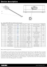
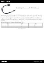
Signal direction definition:
O - Output from the Active Probe to the target microcontroller
 I - Input to the Active Probe from the target microcontroller

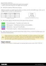
– mDIO port marked as TRIG on the housing 

mDIO port provides two digital signals, which can interact with the embedded target. Each can be
configured either for input or output operation.

Number

Name

Pin1

IOØ

Pin2

IO1

Pin3

GND

mDIO port pinout

mDIO port on the Active Probe

– The indicator light provides the status of the Active Probe as follows:

Permanently green – Powered on and ready to use.

Blinking green – Establishing connection with the BlueBox.

Blinking blue – Reprogramming SPLASH.

Permanently magenta – Golden image loaded and ready to use.

– FNet connector, that connects the Active Probe to the iC7max or iC5700. The FNet cable is de-

livered with the Active Probe.

When powering on the  system,  switch  the  BlueBox  on  before  powering  on  the  target.
When powering down the system, power off the target before powering off the BlueBox!
Use only original  accessories  for  powering  and  connecting  with  the  BlueBox.  Consult
with technical support before attempting to use any other accessory.

Target connector 

The target should feature a matching part, for example, Samtec part number: ASP-137973-01.

Summary of Contents for MPC5X

Page 1: ...www tasking com MPC5X SPC5X AURORA ACTIVE PROBE HARDWARE USER MANUAL V2 2 March 2024...

Page 2: ...avoid potential damage caused by any voltage difference between the device and the target system Use proper overvoltage protection Ensure proper protection to avoid exposing the BlueBox device or the...

Page 3: ...www tasking com Contents Package content 4 Specifications 5 Device description 6 mDIO Cable 8 14 pin 2 54mm JTAG Converter 9 Hardware Setup and Configuration 10 Accessories 11...

Page 4: ...www tasking com Package content The MPC5x SPC5x Aurora Active Probe is delivered with the following components MPC5x SPC5x Active Probe 1m FNet Cable Ordering code IC57150 Ordering code BB FNET 100...

Page 5: ...ength 31 cm OPERATION Communication inter face to BlueBox TASKING proprietary FNet Debug signal valid input voltage range 3 3V max 3 6V Power consumption Max 1 5W dependent on operation mode Number of...

Page 6: ...D Ground Not Connected NC 25 26 AGBT CLK_P AGBT Clock O Not Connected NC 27 28 AGBT CLK_N AGBT Clock O Ground GND 29 30 GND Ground Not Connected NC 31 32 NC Not Connected Not Connected NC 33 34 NC Not...

Page 7: ...reen Powered on and ready to use Blinking green Establishing connection with the BlueBox Blinking blue Reprogramming SPLASH Permanently magenta Golden image loaded and ready to use D FNet connector th...

Page 8: ...ead or controlled by the debugger For example the de bugger can periodically service an external watchdog through the mDIO output or just read and re cord an external signal through the mDIO input It...

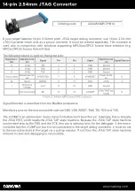
Page 9: ...ORESET Power On Re set O IO Reset nRESET 9 10 TMS JTAG O I Reference Voltage Vref 11 12 GND Ground Not Connected NC 13 14 nJCOMP JTAG TRST op tional O 14 pin 2 54mm MPC5xxx SPC5 pinout Signal Directio...

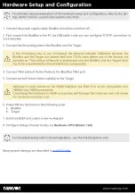
Page 10: ...s are powered up This voltage difference is discharged over the BlueBox and the Target lead ing to the possible destruction of electronic components 4 Connect FNet cable of Active Probe to the BlueBlu...

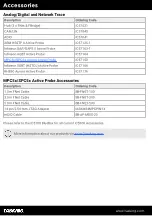
Page 11: ...MPC5x SPC5x Aurora Active Probe IC57150 Infineon SGBT HSTCU Active Probe IC57166 RH850 Aurora Active Probe IC57176 MPC5x SPC5x Active Probe Accessories Description Ordering Code 1 0m FNet Cable BB FN...

Page 12: ...www tasking com www tasking com Visit our website for Support isystem com support Tutorials isystem com start Knowledge Base kb isystem com...

Reviews: