Hardware Description
13
transfer terminates. Both reload registers are set to zero automatically after having been
copied to the DMA pointer and counter registers.
4.16. Debug Unit (DBGU)
The Debug Unit is a simple UART which provides only RX/TX lines. It is used as a simple
serial console for Firmware and Operating Systems.
4.17. JTAG Unit
The JTAG unit can be used for hardware diagnostics, hardware initialization, flash memory
programming, and debug purposes. The JTAG unit supports two different modes, namely
the "ICE Mode", and the "Boundary Scan" mode. It is normally jumpered for "ICE Mode".
JTAG interface devices are available for the unit. However, the use of them is not within
the scope of this document.
4.18. Two-wire Interface (TWI)
The TWI is also known under the expression "I
2
C-Bus", which is a trademark of Philips
and may therefore not be used by other manufacturers. However, interoperability is
guaranteed. The TWI supports both master or slave mode.
The TWI uses only two lines, namely serial data (SDA) and serial clock (SCL). According to
the standard, the TWI clock rate is limited to 400 kHz in fast mode and 100 kHz in normal
mode, but configurable baud rate generator permits the output data rate to be adapted
to a wide range of core clock frequencies.
Caveat: The TWI hardware unit has been known to be error prone in various
microcontrollers, which has lead operating systems like Linux to use a bit-banging driver
on the same pins instead.
4.19. Multimedia Card Interface (MCI)
The Panel-Card features two Multimedia Card Controller, of which MCI-A is externally
available on the connectors. On the Evaluation Board of the Panel-Card 35, it is connected
to the SD/MMC-Card slot. Please note that operating systems like Linux do not necessarily
support all features of the hardware unit.
The MultiMedia Card Interface (MCI) supports the MultiMedia Card (MMC) Specification
V3.11, the SDIO Specification V1.1 and the SD Memory Card Specification V1.0.
The MCI includes a command register, response registers, data registers, timeout
counters and error detection logic that automatically handle the transmission of
commands and, when required, the reception of the associated responses and data with a
limited processor overhead. The MCI supports stream, block and multi-block data read and
write, and is compatible with the Peripheral DMA Controller (PDC) channels, minimizing
processor intervention for large buffer transfers.
The MCI operates at a rate of up to Master Clock divided by 2 and supports the interfacing
of 2 slot(s). Each slot may be used to interface with a MultiMediaCard bus (up to 30 Cards)
Summary of Contents for Panel-Card
Page 1: ...Panel Card Technical Reference ...
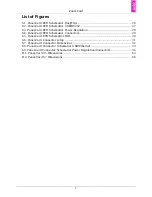
Page 32: ...Panel Card Starterkit 26 Figure 6 1 Panel Card EVB Schematics Bus JTAG ...
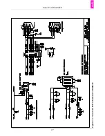
Page 33: ...Panel Card Starterkit 27 Figure 6 2 Panel Card EVB Schematics USB RS232 ...
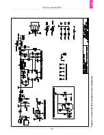
Page 34: ...Panel Card Starterkit 28 Figure 6 3 Panel Card EVB Schematics Power Regulation ...
Page 35: ...Panel Card Starterkit 29 Figure 6 4 Panel Card EVB Schematics Connectors ...
Page 36: ...Panel Card Starterkit 30 Figure 6 5 Panel Card EVB Schematics HID ...
Page 39: ...Panel Card Starterkit 33 Figure 6 8 Panel Card Connector Schematics USB Ethernet ...
Page 49: ...Panel Card Dimensions 43 Appendix H Panel Card Dimensions Figure H 1 Panel Card 35 Dimensions ...
Page 50: ...Panel Card Dimensions 44 Figure H 2 Panel Card 57 Dimensions ...

