Hardware Description
14
or with a SD Memory Card. Only one slot can be selected at a time (slots are multiplexed).
A bit field in the SD Card Register performs this selection.
The SD Memory Card communication is based on a 9-pin interface (clock, command,
four data and three power lines) and the MultiMedia Card on a 7-pin interface (clock,
command, one data, three power lines and one reserved for future use). The SD Memory
Card interface also supports MultiMedia Card operations. The main differences between
SD and MultiMedia Cards are the initialization process and the bus topology.
4.20. USB Host Port (UHP)
The Panel-Card integrates two USB host ports supporting speeds up to 12 MBit/s.
The USB Host Port (UHP) interfaces the USB with the host application. It handles Open
HCI protocol (Open Host Controller Interface) as well as USB v2.0 Full-speed and Low-
speed protocols.
The USB Host Port integrates a root hub and transceivers on downstream ports. It
provides several high-speed half-duplex serial communication ports. Up to 127 USB
devices (printer, camera, mouse, keyboard, disk, etc.) and an USB hub can be connected
to the USB host in the USB "tiered star" topology.
4.21. USB Device Port (UDP)
The Panel-Card integrates one USB device port supporting speeds up to 12 MBit/s.
The USB Device Port (UDP) is compliant with the Universal Serial Bus (USB) V2.0 full-
speed device specification. The USB device port enables the product to act as a device
to other host controllers.
The USB device port can also be implemented to power on the board. One I/O line may be
used by the application to check that VBUS is still available from the host. Self-powered
devices may use this entry to be notified that the host has been powered off. In this case,
the pullup on DP must be disabled in order to prevent feeding current to the host. The
application should disconnect the transceiver, then remove the pullup.
4.22. Universal Sychronous Asynchronous Receiver and
Transmitter (USART)
The Panel-Card has up to three independent USARTs, not including the debug unit.
The Universal Synchronous Asynchronous Receiver Transceiver (USART) provides one
full duplex universal synchronous asynchronous serial link. Data frame format is widely
programmable (data length, parity, number of stop bits) to support a maximum of
standards. The receiver implements parity error, framing error and overrun error
detection. The receiver time-out enables handling variable-length frames and the
transmitter timeguard facilitates communications with slow remote devices. Multidrop
communications are also supported through address bit handling in reception and
transmission.
Summary of Contents for Panel-Card
Page 1: ...Panel Card Technical Reference ...
Page 32: ...Panel Card Starterkit 26 Figure 6 1 Panel Card EVB Schematics Bus JTAG ...
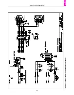
Page 33: ...Panel Card Starterkit 27 Figure 6 2 Panel Card EVB Schematics USB RS232 ...
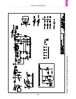
Page 34: ...Panel Card Starterkit 28 Figure 6 3 Panel Card EVB Schematics Power Regulation ...
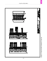
Page 35: ...Panel Card Starterkit 29 Figure 6 4 Panel Card EVB Schematics Connectors ...
Page 36: ...Panel Card Starterkit 30 Figure 6 5 Panel Card EVB Schematics HID ...
Page 39: ...Panel Card Starterkit 33 Figure 6 8 Panel Card Connector Schematics USB Ethernet ...
Page 49: ...Panel Card Dimensions 43 Appendix H Panel Card Dimensions Figure H 1 Panel Card 35 Dimensions ...
Page 50: ...Panel Card Dimensions 44 Figure H 2 Panel Card 57 Dimensions ...


