Hardware Description
16
• Iteration: the maximum number of repetitions has been reached (ISO7816 mode only)
Please refer to the chapter about the DMA unit (PDC) for a description of the "Buffer Full"
and "End of Receive / Transmit Buffer" events.
4.23. Synchronous Peripheral Interface (SPI)
The Panel-Card features two externally available SPI ports, each with three chip selects.
Be aware that on the Panel-Card 35 when connected to the Evaluation Board and on the
Panel-Card 57/70 all chip selects of the second port are already used. To compensate for
this, you can also use GPIO pins as chip selects with the Linux SPI driver. Additionally the
first SPI port is multiplexed with the MMC controller.
The Serial Peripheral Interface (SPI) circuit is a synchronous serial data link that
provides communication with external devices in Master or Slave Mode. It also enables
communication between processors if an external processor is connected to the system.
The Serial Peripheral Interface is essentially a shift register that serially transmits data
bits to other SPIs. During a data transfer, one SPI system acts as the "master" which
controls the data flow, while the other devices act as "slaves" which have data shifted into
and out by the master.
A slave device is selected when the master asserts its NSS signal. If multiple slave devices
exist, the master generates a separate slave select signal for each slave (NPCS). The SPI
system consists of two data lines and two control lines:
• Master Out Slave In (MOSI): This data line supplies the output data from the master
shifted into the input(s) of the slave(s).
• Master In Slave Out (MISO): This data line supplies the output data from a slave to the
input of the master. There may be no more than one slave transmitting data during any
particular transfer.
• Serial Clock (SPCK): This control line is driven by the master and regulates the flow of
the data bits. The master may transmit data at a variety of baud rates; the SPCK line
cycles once for each bit that is transmitted. The SPI baudrate is Master Clock (MCK)
divided by a value between 1 and 255
• Slave Select (NSS): This control line allows slaves to be turned on and off by hardware.
Each SPI Controller has a dedicated receive and transmit DMA channel.
4.24. Peripheral Input/Output Controller (PIO)
The Panel-Card has a maximum of 40 freely programmable digital I/O ports on its
connectors. These pins are also used by other peripheral devices.
The Parallel Input/Output Controller(PIO) manages up to 32 programmable I/O ports. Each
I/O port is associated with a bit number in the 32 bit register of the user interface. Each I/O
port may be configured for general purpose I/O or assigned to a function of an integrated
peripheral device. In doing so multiplexing with 2 integrated devices is possible. That
Summary of Contents for Panel-Card
Page 1: ...Panel Card Technical Reference ...
Page 32: ...Panel Card Starterkit 26 Figure 6 1 Panel Card EVB Schematics Bus JTAG ...
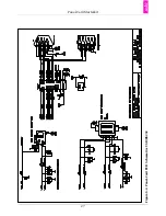
Page 33: ...Panel Card Starterkit 27 Figure 6 2 Panel Card EVB Schematics USB RS232 ...
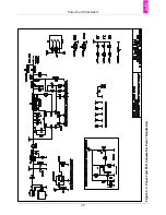
Page 34: ...Panel Card Starterkit 28 Figure 6 3 Panel Card EVB Schematics Power Regulation ...
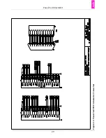
Page 35: ...Panel Card Starterkit 29 Figure 6 4 Panel Card EVB Schematics Connectors ...
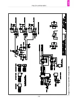
Page 36: ...Panel Card Starterkit 30 Figure 6 5 Panel Card EVB Schematics HID ...
Page 39: ...Panel Card Starterkit 33 Figure 6 8 Panel Card Connector Schematics USB Ethernet ...
Page 49: ...Panel Card Dimensions 43 Appendix H Panel Card Dimensions Figure H 1 Panel Card 35 Dimensions ...
Page 50: ...Panel Card Dimensions 44 Figure H 2 Panel Card 57 Dimensions ...

