Panel-Card Starterkit
25
The rotary encoder is accessed by two PIO ports of the module (see circuit diagram). The
push-button occupies another PIO port.
6.2.6. Touch Controller
The Panel-Card EVB implements a ADS7843 Touch controller. It is connected to SPI of the
module. The touch controller and the rotary encoder can only be used mutually exclusive.
Connect jumper J2 to ID for the rotary encoder and to TP for touch.
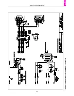
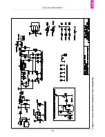
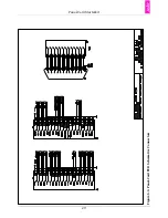
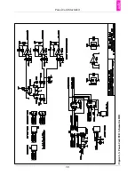
6.2.7. Schematics
The following circuit diagram is intended for reference only and does not dispense the
user from checking and applying the appropriate standards. No warranty can be granted
if parts of the circuit are used in customer applications.
Summary of Contents for Panel-Card
Page 1: ...Panel Card Technical Reference ...
Page 32: ...Panel Card Starterkit 26 Figure 6 1 Panel Card EVB Schematics Bus JTAG ...
Page 33: ...Panel Card Starterkit 27 Figure 6 2 Panel Card EVB Schematics USB RS232 ...
Page 34: ...Panel Card Starterkit 28 Figure 6 3 Panel Card EVB Schematics Power Regulation ...
Page 35: ...Panel Card Starterkit 29 Figure 6 4 Panel Card EVB Schematics Connectors ...
Page 36: ...Panel Card Starterkit 30 Figure 6 5 Panel Card EVB Schematics HID ...
Page 39: ...Panel Card Starterkit 33 Figure 6 8 Panel Card Connector Schematics USB Ethernet ...
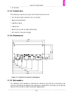
Page 49: ...Panel Card Dimensions 43 Appendix H Panel Card Dimensions Figure H 1 Panel Card 35 Dimensions ...
Page 50: ...Panel Card Dimensions 44 Figure H 2 Panel Card 57 Dimensions ...


