Panel-Card Starterkit
31
6.3. Panel-Card Connector
The Panel-Card Connector was designed to serve the Panel-Card 57/70 as an evaluation
platform and as a deployable base board for all Panel-Cards. It can also be used to develop
and deploy Stamp9261 and Stamp9G20 systems.
6.3.1. First Steps
The Panel-Card Connector makes it easy to put the Panel-Card/Stamp to use. The first
steps involve the following:
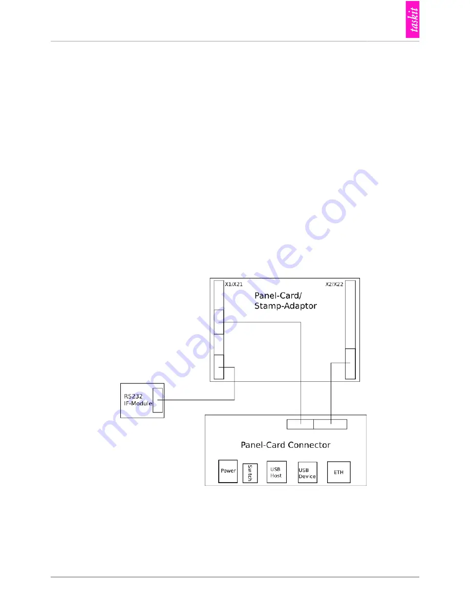
• connecting the board to the Panel-Card/Stamp-Adaptor according to Figure 6.6, “Panel-
Card Connector setup”
• connecting the wall adapter to the main supply and to the board
• connecting RS232 IF-Module via the serial cable to a COM port of a PC
• starting a terminal program for the selected COM port at 115200 baud, 8N1
• starting the module by flipping the power switch
• boot messages of the module are now expected to appear on the terminal
Figure 6.6. Panel-Card Connector setup
6.3.2. Power Supply
From an unregulated input voltage between 8 and 35V two voltages are produced:
• 3.3V for the CPU module
Summary of Contents for Panel-Card
Page 1: ...Panel Card Technical Reference ...
Page 32: ...Panel Card Starterkit 26 Figure 6 1 Panel Card EVB Schematics Bus JTAG ...
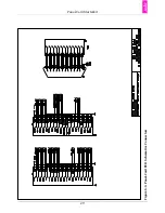
Page 33: ...Panel Card Starterkit 27 Figure 6 2 Panel Card EVB Schematics USB RS232 ...
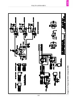
Page 34: ...Panel Card Starterkit 28 Figure 6 3 Panel Card EVB Schematics Power Regulation ...
Page 35: ...Panel Card Starterkit 29 Figure 6 4 Panel Card EVB Schematics Connectors ...
Page 36: ...Panel Card Starterkit 30 Figure 6 5 Panel Card EVB Schematics HID ...
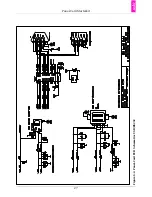
Page 39: ...Panel Card Starterkit 33 Figure 6 8 Panel Card Connector Schematics USB Ethernet ...
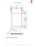
Page 49: ...Panel Card Dimensions 43 Appendix H Panel Card Dimensions Figure H 1 Panel Card 35 Dimensions ...
Page 50: ...Panel Card Dimensions 44 Figure H 2 Panel Card 57 Dimensions ...


