TATSUNO
EUROPE
a.s.,
www.tatsuno
‐
europe.com
96
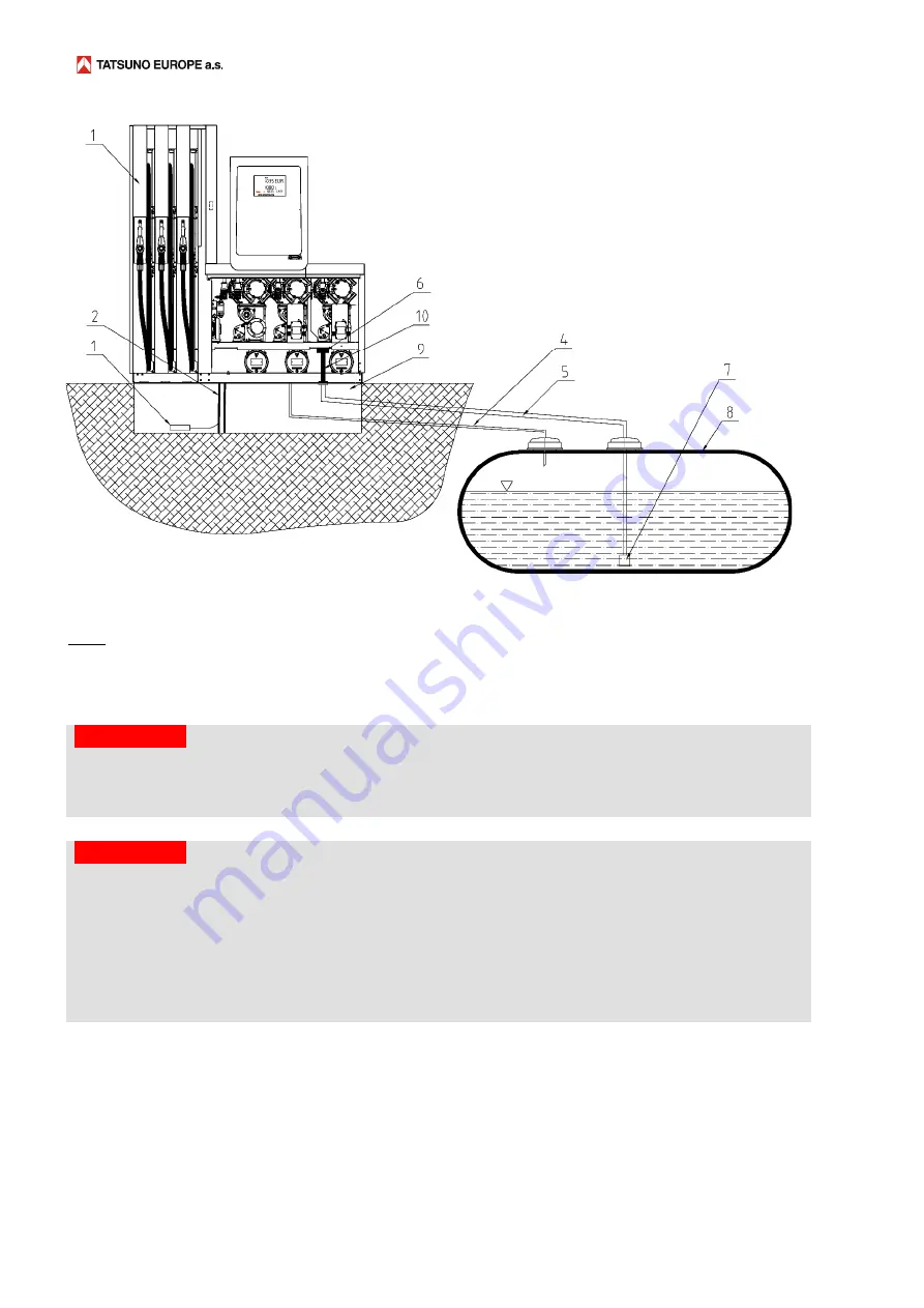
Picture
72–
Example
of
connection
of
the
dispenser
with
suction
pumps
to
an
underground
tank
Legend:
1
–
dispenser,
2
–
electrical
supply
cables
and
data
line,
3
–
liquid
sensor
located
at
the
bottom
of
the
drip
tray,
4
–
vapor
return
pipe
(recuperation),
5
–
suction
fuel
pipe,
6
–
check
valve
at
the
pump
inlet,
7
–
suction
basket
(without
non
‐
return
valve),
8
–
underground
fuel
tank,
9
–
drip
tray
with
dispenser
base
frame,
10
–
connection
piece
(bellows)
with
flange
CAUTION
B&D
If
the
dispenser
is
connected
to
an
underground
storage
tank
,
it
is
necessary
to
include
a
backflow
valve
in
the
suction
pipeline
to
ensure
that
if
the
dispenser
is
stationary
and
does
not
pump,
the
fuel
column
will
not
be
spontaneously
interrupted
and
the
air
will
not
be
sucked
in
after
pumping
starts.
A
separate
check
valve
must
not
be
installed
if
a
suction
basket
has
been
already
equipped
with
a
check
valve
(see
Picture
72)
CAUTION
B&D
If
the
dispenser
is
connected
to
an
aboveground
storage
tank,
it
is
necessary
for
the
safety
reasons
to
include
a
pressure
relief
(check)
valve
in
the
suction
pipeline
which
prevents
the
product
from
escaping
from
the
tank
by
gravity
during
a
malfunction.
The
valve
also
serves
to
release
overpressure
in
the
suction
pipeline
back
into
the
storage
tank.
We
recommend
the
OPW
199ASV
(Anti
‐
Siphon
Valve)
valve.
The
valve
type
must
be
selected
according
to
the
difference
between
the
maximum
fuel
level
in
the
storage
tank
and
the
lowest
point
of
the
fuel
line,
see
Picture
73
–
height
A.
At
the
lowest
point
of
the
pipeline,
a
shut
‐
off
and
drain
valve
should
be
installed
which
should
be
closed
by
the
fuel
station
operator
whenever
the
dispenser
is
not
in
operation.
In
the
absence
of
these
valves,
uncontrolled
leakage
of
fuel
can
occur
in
the
event
of
any
leak
in
the
piping
system!
(see
Picture
73).


