background image

14

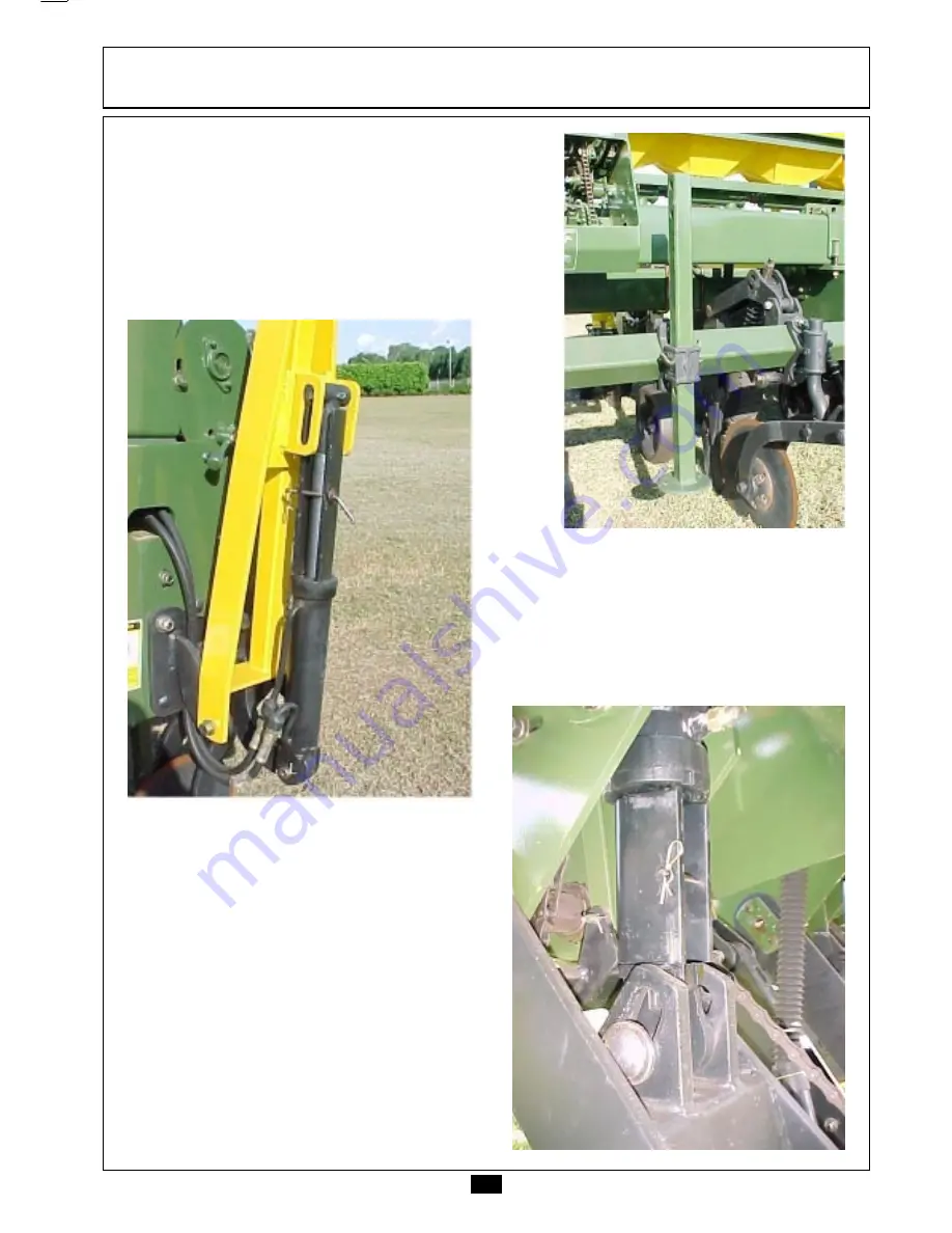
Putting the Planter in Transport

Position

Raise the planter totally and lift the

stands up.

SET

SET

SET

SET

SET-UP INSTRUCTIONS

-UP INSTRUCTIONS

-UP INSTRUCTIONS

-UP INSTRUCTIONS

-UP INSTRUCTIONS

Place the safety locks of the row

markers.

Place the safety locks into the

hydraulic cylinders rod.

Summary of Contents for COP 11

Page 1: ...rtilizer distribution is done with auger type metering guaranteeing an uniform distribution in all the row units The calibration for different rates of fertilizer and seed is easily obtained by the sprocket combination mechanism without using any tools The seed depth control is done through the oscillating rubber wheels that accompany the ground and favor the plants emergence for equal This Manual...

Page 2: ... for fertilizer distribution 53 Oscillating coulter blades No Till 54 Fertilizer furrow opening 54 and 55 Seed furrow opening 56 Adjusting the press wheels 57 Auxiliary depth control 58 Instructions for half planter working 58 Row markers and disc working angle 59 and 60 OPERATIONS Important points 61 OPTIONAL 62 and 63 Seed plates 62 Attachment for two planters 63 MAINTENANCE 64 to 70 Lubrication...

Page 3: ...n equipment which is properly lubricated and adjusted saves you time labor and fuel IMPORTANT ONLY PERSON WHO OWNS A FULL KNOWLEDGE OF THE TRACTOR AND IMPLEMENT MUST OPERATE THEM MARCHESAN IS NOT RESPONSIBLE FOR ANY DAMAGE CAUSED BY ACCIDENT ON TRANSPORT INCORRECT UTILIZATION OR NO ADEQUATE STORAGE AFTER THE OPERATING SEASON THOROUGHLY CLEAN YOUR IMPLEMENT AND INSPECT IT PREVENTIVE MAINTENANCE PAY...

Page 4: ...h away This gesture of goodwill helps to protect our Environment Do not spill combustible oil battery and filter residues in the soil The trash in contact with the soil reach the sub layer which directly damage to the Environment Look for information to delivery these contaminated elements to whom knows how to recycle or re use them The COP Planters are easy to operate therefore some basic and ind...

Page 5: ...lean and free of the oil and grease to p r e v e n t accidents Never transport the implement on rough roads during the night when operating avoid to make sharp turns that may cause tire to make contact with implement Never allow riders on the tractor or implement unless an additional seat is available Use extreme caution when circulating with the implement under electrical power lines any contact ...

Page 6: ...lean and replace them when it s necessary Read the manual before attempting to work with the equipment Lea el manual antes de iniciar el uso del equipo 0503031779 C A U T I O N AT E N C I O N WARNING ADVERTENCIA Use the SAFETY LOCKS before adjusting or servicing under the planter Utilice las TRABAS DE SEGURIDAD antes de efectuar ajustes o mantención debajo de la sembradora AVOID ACCIDENTS EVITE AC...

Page 7: ...almacenar o efectuar servicios de mantención WARNING ADVERTENCIA 0503031782 WARNING ADVERTENCIA 0503031781 PRECAUTIONS DURING WORKING AND TRANSPORTATION The ladders to the platform must be raised Never transport any person on the ladders seat platform or any planter parts PRECAUTIONS DURINGADJUSTMENTS All the protection guards must be kept in place and in good conditions to avoid accidents CUIDADO...

Page 8: ... the back cover of this Manual When Transporting the Implement on Truck or Trailer To transport the equipment at long distances use a truck or trailer However the safety instructions should be followed carefully Use adequate loading dock to load and unload the equipment Never use a ditch bank this practice could result in serious personal injury In the event of lifting up with hoist use the approp...

Page 9: ...0 15 7 950 434 350 4 256 4 476 15 8 750 800 850 or 900 496 400 4 458 4 678 15 10 650 or 700 6 300 620 500 4 862 5 082 120 140 170 195 15 12 500 or 550 744 600 5 266 5 486 15 15 400 or 450 930 750 5 670 5 890 17 7 950 434 350 4 692 4 584 17 8 850 496 400 4 894 4 828 17 9 850 or 900 558 450 5 096 5 064 17 10 700 750 or 800 7 200 620 500 5 298 5 308 150 180 200 230 17 12 650 744 600 5 702 5 796 17 14...

Page 10: ... 4 740 1 950 1 100 1 400 15 7 140 6 640 2 300 3 120 4 740 1 950 1 100 1 400 17 8 040 7 540 2 300 3 120 4 740 1 950 1 100 1 400 19 8 800 8 500 2 300 3 120 4 740 1 950 1 100 1 400 Dimensions in milimeters A C D E G F B TECHNICAL SPECIFICA TECHNICAL SPECIFICA TECHNICAL SPECIFICA TECHNICAL SPECIFICA TECHNICAL SPECIFICATIONS TIONS TIONS TIONS TIONS COP COP SUPREMA COP SUPREMA COP Row Markers ChassiOuts...

Page 11: ...ome detached parts just remaining the placement of those components according to orientations to proceed Drawbar Assembling Install the drawbar on the planter frame using the pins and locks A Install the stabilizer B between the drawbar and the frame Install the hoses C Install the hose guard D ...

Page 12: ...OR ANIMALS IN THE ROW MARKERS ACTION AREA Assembly of the Row Units Assemble the row units using bolts A supplied inside the detached parts packing box Row Markers Assembly Install the arms and disc markers Note THE ROW MARKERS POSSESS SYNCHRONIZED MOVEMENTS WITH THE RAISING AND LOWERING PLANTER MOVEMENTS ...

Page 13: ...th pin and lock If necessary use the planter stabilizer to raise or lower the hitch The tractor drawbar must be allways fixed in the center position Clean and connect the hose couplers to the tractor hydraulic system Leveling the Planter Through the stabilizer make the planter leveling after coupling to the tractor To facilitate the stabilizer handling it is enough to work the hydraulic cylinder a...

Page 14: ...Raise the planter totally and lift the stands up SET SET SET SET SET UP INSTRUCTIONS UP INSTRUCTIONS UP INSTRUCTIONS UP INSTRUCTIONS UP INSTRUCTIONS Place the safety locks of the row markers Place the safety locks into the hydraulic cylinders rod ...

Page 15: ...ssis Even number of rows Mark The center of the chassis From this mark you have to measure half spacing to the right and half to the left installing in these points the first two rows From these rows you mark the others with a spacing to each side Odd number of rows Install one row unit in the center of the chassis From this row you mark the others with a spacing to each side SET SET SET SET SET U...

Page 16: ...UCTIONS UP INSTRUCTIONS UP INSTRUCTIONS UP INSTRUCTIONS COP COP SUPREMA 7 7 400 mm row spacing COP COP SUPREMA 7 7 450 mm row spacing COP COP SUPREMA 7 6 500 mm row spacing COP COP SUPREMA 7 6 550 mm row spacing COP COP SUPREMA 7 6 600 mm row spacing COP COP SUPREMA 7 4 700 mm row spacing ...

Page 17: ...NSTRUCTIONS UP INSTRUCTIONS UP INSTRUCTIONS UP INSTRUCTIONS UP INSTRUCTIONS COP COP SUPREMA 7 4 750 mm row spacing COP COP SUPREMA 7 4 800 mm row spacing COP COP SUPREMA 7 4 850 mm row spacing COP COP SUPREMA 7 4 900 mm row spacing COP COP SUPREMA 7 4 950 mm row spacing ...

Page 18: ...UCTIONS UP INSTRUCTIONS UP INSTRUCTIONS UP INSTRUCTIONS COP COP SUPREMA 9 9 400 mm row spacing COP COP SUPREMA 9 9 450 mm row spacing COP COP SUPREMA 9 7 500 mm row spacing COP COP SUPREMA 9 7 550 mm row spacing COP COP SUPREMA 9 6 550 mm row spacing COP COP SUPREMA 9 6 600 mm row spacing ...

Page 19: ... UP INSTRUCTIONS COP COP SUPREMA 9 6 650 mm row spacing COP COP SUPREMA 9 6 700 mm row spacing COP COP SUPREMA 9 6 750 mm row spacing COP COP SUPREMA 9 5 750 mm row spacing COP COP SUPREMA 9 5 800 mm row spacing COP COP SUPREMA 9 5 850 mm row spacing COP COP SUPREMA 9 5 900 mm row spacing COP COP SUPREMA 9 4 950 mm row spacing ...

Page 20: ...ONS UP INSTRUCTIONS UP INSTRUCTIONS UP INSTRUCTIONS COP COP SUPREMA 11 11 400 mm row spacing COP COP SUPREMA 11 11 450 mm row spacing COP COP SUPREMA 11 10 500 mm row spacing COP COP SUPREMA 11 8 550 mm row spacing COP COP SUPREMA 11 8 600 mm row spacing COP COP SUPREMA 11 8 650 mm row spacing ...

Page 21: ...IONS UP INSTRUCTIONS UP INSTRUCTIONS UP INSTRUCTIONS COP COP SUPREMA 11 6 700 mm row spacing COP COP SUPREMA 11 6 750 mm row spacing COP COP SUPREMA 11 6 800 mm row spacing COP COP SUPREMA 11 6 850 mm row spacing COP COP SUPREMA 11 6 900 mm row spacing COP COP SUPREMA 11 5 950 mm row spacing ...

Page 22: ...SET SET SET UP INSTRUCTIONS UP INSTRUCTIONS UP INSTRUCTIONS UP INSTRUCTIONS UP INSTRUCTIONS COP COP SUPREMA 13 13 400 mm row spacing COP COP SUPREMA 13 13 450 mm row spacing COP COP SUPREMA 13 8 650 mm row spacing COP COP SUPREMA 13 10 550 mm row spacing ...

Page 23: ...ONS UP INSTRUCTIONS UP INSTRUCTIONS UP INSTRUCTIONS Positioning the Row Units in the Chassis COP COP SUPREMA 13 8 700 mm row spacing COP COP SUPREMA 13 8 750 mm row spacing COP COP SUPREMA 13 7 850 mm row spacing COP COP SUPREMA 13 7 800 mm row spacing ...

Page 24: ...UCTIONS UP INSTRUCTIONS UP INSTRUCTIONS UP INSTRUCTIONS UP INSTRUCTIONS Positioning the Row Units in the Chassis COP COP SUPREMA 13 7 900 mm row spacing COP COP SUPREMA 13 6 900 mm row spacing COP COP SUPREMA 13 5 950 mm row spacing ...

Page 25: ...S UP INSTRUCTIONS UP INSTRUCTIONS UP INSTRUCTIONS Positioning the Row Units in the Chassis COP COP SUPREMA 15 15 400 mm row spacing COP COP SUPREMA 15 12 500 mm row spacing COP COP SUPREMA 15 15 450 mm row spacing COP COP SUPREMA 15 12 550 mm row spacing ...

Page 26: ...SET SET SET UP INSTRUCTIONS UP INSTRUCTIONS UP INSTRUCTIONS UP INSTRUCTIONS UP INSTRUCTIONS COP COP SUPREMA 15 10 650 mm row spacing COP COP SUPREMA 15 8 750 mm row spacing COP COP SUPREMA 15 10 700 mm row spacing COP COP SUPREMA 15 8 800 mm row spacing ...

Page 27: ... the Chassis SET SET SET SET SET UP INSTRUCTIONS UP INSTRUCTIONS UP INSTRUCTIONS UP INSTRUCTIONS UP INSTRUCTIONS COP COP SUPREMA 15 8 850 mm row spacing COP COP SUPREMA 15 7 950 mm row spacing COP COP SUPREMA 15 8 900 mm row spacing ...

Page 28: ...ET SET SET UP INSTRUCTIONS UP INSTRUCTIONS UP INSTRUCTIONS UP INSTRUCTIONS UP INSTRUCTIONS COP COP SUPREMA 17 17 400 mm row spacing COP COP SUPREMA 17 14 500 mm row spacing COP COP SUPREMA 17 17 450 mm row spacing COP COP SUPREMA 17 14 550 mm row spacing ...

Page 29: ...NS UP INSTRUCTIONS UP INSTRUCTIONS UP INSTRUCTIONS Positioning the Row Units in the Chassis COP COP SUPREMA 17 12 650 mm row spacing COP COP SUPREMA 17 10 750 mm row spacing COP COP SUPREMA 17 10 700 mm row spacing COP COP SUPREMA 17 7 950 mm row spacing ...

Page 30: ...ONS UP INSTRUCTIONS UP INSTRUCTIONS UP INSTRUCTIONS Positioning the Row Units in the Chassis COP COP SUPREMA 17 10 800 mm row spacing COP COP SUPREMA 17 9 900 mm row spacing COP COP SUPREMA 17 9 850 mm row spacing COP COP SUPREMA 17 8 850 mm row spacing ...

Page 31: ... INSTRUCTIONS UP INSTRUCTIONS Positioning the Row Units in the Chassis COP COP SUPREMA 19 19 450 mm row spacing COP COP SUPREMA 19 14 550 mm row spacing COP COP SUPREMA 19 16 500 mm row spacing COP COP SUPREMA 19 13 600 mm row spacing COP COP SUPREMA 19 15 550 mm row spacing ...

Page 32: ...S UP INSTRUCTIONS UP INSTRUCTIONS UP INSTRUCTIONS Positioning the Row Units in the Chassis COP COP SUPREMA 19 13 650 mm row spacing COP COP SUPREMA 19 10 750 mm row spacing COP COP SUPREMA 19 12 700 mm row spacing COP COP SUPREMA 19 10 780 mm row spacing ...

Page 33: ...SET SET SET UP INSTRUCTIONS UP INSTRUCTIONS UP INSTRUCTIONS UP INSTRUCTIONS UP INSTRUCTIONS COP COP SUPREMA 19 10 800 mm row spacing COP COP SUPREMA 19 10 900 mm row spacing COP COP SUPREMA 19 10 850 mm row spacing COP COP SUPREMA 19 9 890 mm row spacing ...

Page 34: ...ting the wheels Dislocate the carrying wheels in the chassis as well as the driving components until the desired positions Raise the planter and place the threaded adjusting rods A in the cylinders being this way locked and free for the row units displacement Note READ HOW TO TIGHTEN THE ROW UNITS ON THE PAGE 36 For models 9 4 to 19 19 For changing the spacing among the row units raise the planter...

Page 35: ...UP INSTRUCTIONS 3rd Loose the bolts A of the hexagonal bars and remove the cotter pins B A 4th Remove the hexagonal bars completely 5th Loose the nuts that hold the row units to displace them in the chassis 6th Dislocate the carrying wheels and the transmission clutches Dislocate the coulter blades and the fertilizer row units B ...

Page 36: ... WITH BUSHINGS THAT FIX THE HEXAGONAL BARS WILL BE MADE AT LAST VERIFY THE CORRECT ALIGNMENT OF THE CHAINS CARRYING WHEELS TO THE CLUTCHES Procedures for Changing the Row Spacings 7th In order to close some fertilizer metering fit the detachable cover to the augers that won t be used SET SET SET SET SET UP INSTRUCTIONS UP INSTRUCTIONS UP INSTRUCTIONS UP INSTRUCTIONS UP INSTRUCTIONS 8th In order to...

Page 37: ...s according to the local working conditions See the slippage index calculation for the planter in your field conditions This index is obtained by comparing the amount of planter carrying wheel turns when hoppers are empty with filled hoppers by running the planter in the field With the planter empty and usually attached to the tractor mark a starting point in the ground and in the planter carrying...

Page 38: ...ntaining Germination Index 95 Physical purity 90 and Slippage Index 1 03 3 the following calculation should be made to know how many seeds should be distributed in a hectare Seeds ha at the planting time 50 000 58 479 5 x 1 03 60 233 88 0 95 x 0 90 To know the amount of seeds per meter per 10 meters etc calculate how many linear meters of rows exist in a hectare in the desired spacing Example 10 0...

Page 39: ...3 0 MM USING PLATES OF 8 5 MM THICKNESS DON T USE ANY FALSE RING Use of Powdered Graphite The powdered graphite should be mixed to the seeds to facilitate the distribution and to increase the mechanism distributor useful life AMOUNT OF GRAPHITE PER KILOGRAM OF SEED Kind of Seed metering system Seeds with chemical treatment Round and Bigger Round and Smaller Flattened Seed Plate 04 grams 02 grams 0...

Page 40: ...ELLS FOR EXAMPLE CORN IN ROUND SHAPE SOYBEAN DELINTED COTTON BEAN ETC THE PLATE FOR CORN WITH SLOTS DEMANDS A KNOCKER WITH 4 TOOTH THAT FOLLOWS SEPARATED FOR PLANTING SORGHUM IT IS NECESSARY TO USE SPECIAL KNOCKER SO THAT THEY ENTER IN THE CELLS AND EXECUTE THEIR FUNCTION FOR THE SOYBEAN PLATE WITH TWO ROWS OF CELLS IT IS NECESSARY TO USE THE DOUBLE KNOCKER WITH TWO EJECTORS SET SET SET SET SET UP...

Page 41: ...CALIBRATION FACTORS AS SLIPPAGE INDEX OF THE PLANTER CARRYING WHEELS SKIDDING WORKING SPEED TIRES INFLATION AND FIELD CONDITIONS CAN INTRODUCE VALUES A LITTLE DIFFERENT FROM THOSE INDICATED IN THE TABLES THEREFORE IT IS ALWAYS INDISPENSABLE TO MAKE THE PRACTICAL DISTRIBUTION TESTS AS INDICATED ON THE PAGE 52 OF THIS MANUAL Procedures for the Sprockets Handling Move the lever to alleviate the chain...

Page 42: ...34 22 60 8 38 22 68 0 25 14 70 3 34 17 78 7 38 17 88 0 34 14 95 6 38 14 106 9 SPROCKETS AMOUNT OF DRIVE DRIVEN SEEDS IN SHAFT A SHAFT B 10 LINEAR METERS NOTE USE FALSE RING OF 4 0 MM THICKNESS IN THE TABLE IT HAS BEEN CONSIDERED ONE 01 SEED PER CELL CORN Standard Seed Plates Part 0502020519 Seed Plate with 4 5 mm thickness and 28 cell Ø 13 5 mm For flat and short seeds Part 0502020518 Seed Plate w...

Page 43: ...4 30 14 3 25 22 14 4 34 28 15 4 21 17 15 6 38 30 16 0 38 28 17 2 25 17 18 6 21 14 19 0 34 22 19 6 38 22 21 9 25 14 22 6 34 17 25 3 38 17 28 3 34 14 30 7 38 14 34 3 SPROCKETS AMOUNT OF DRIVE DRIVEN SEEDS PER SHAFT A SHAFT B 1 LINEAR METER NOTE USE FALSE RING OF 3 0 MM THICKNESS IN THE TABLE IT HAS BEEN CONSIDERED ONE 01 SEED PER CELL SOYBEAN Standard Seed Plates Part 0502020565 Seed Plate with 5 5 ...

Page 44: ...7 17 17 11 2 34 30 12 7 25 22 12 8 34 28 13 7 21 17 13 9 38 30 14 2 38 28 15 3 25 17 16 5 21 14 16 9 34 22 17 4 38 22 19 4 25 14 20 1 34 17 22 5 38 17 25 1 34 14 27 3 38 14 30 5 NOTE USE FALSE RING OF 3 0 MM THICKNESS IN THE TABLE IT HAS BEEN CONSIDERED TWO 02 SEEDS PER CELL SOYBEAN Optional Seed Plate Part 0502020407 Seed Plate with 5 5 mm thickness and 40 cell 9 x 14 mm SPROCKETS AMOUNT OF DRIVE...

Page 45: ...21 30 16 7 21 28 17 9 17 22 18 5 25 30 19 9 25 28 21 3 21 22 22 8 17 17 23 9 34 30 27 1 25 22 27 2 34 28 29 0 21 17 29 5 38 30 30 3 38 28 32 4 25 17 35 2 21 14 35 9 34 22 36 9 38 22 41 3 25 14 42 7 34 17 47 8 38 17 53 4 34 14 58 1 38 14 64 9 DRIVE SHAFT A SPROCKETS DRIVEN SHAFT B AMOUNT OF SEEDS PER 1 LINEAR METER 2 SEEDS 1 SEED PER CELL PER CELL NOTE IN THE TABLE IT HAS BEEN CONSIDERED FIVE 05 SE...

Page 46: ...SEED PER CELL PER CELL 17 30 9 1 6 1 17 28 9 7 6 5 21 30 11 2 7 5 21 28 12 0 8 0 17 22 12 4 8 3 25 30 13 4 8 9 25 28 14 3 9 5 21 22 15 3 10 2 17 17 16 0 10 7 34 30 18 2 12 1 25 22 18 2 12 1 34 28 19 5 13 0 21 17 19 8 13 2 38 30 20 3 13 5 38 28 21 8 14 5 25 17 23 6 15 7 21 14 24 0 16 0 34 22 24 8 16 5 38 22 27 7 18 5 25 14 28 6 19 1 34 17 32 1 21 4 38 17 35 8 23 9 34 14 38 9 26 0 38 14 43 5 29 0 DR...

Page 47: ... 34 28 6 8 21 17 6 9 38 30 7 1 38 28 7 6 25 17 8 3 21 14 8 4 34 22 8 7 38 22 9 7 25 14 10 0 34 17 11 2 38 17 12 6 34 14 13 7 38 14 15 3 NOTE USE FALSE RING OF 4 0 MM THICKNESS IN THE TABLE IT HAS BEENCONSIDERED ONE 01 SEED PER CELL BEAN and DELINTED COTTON Optional Seed Plate Part 0502020419 Seed Plate with 4 5 mm thickness and 40 cell 7 x 12 mm SPROCKETS AMOUNT OF DRIVE DRIVEN SEEDS PER SHAFT A S...

Page 48: ...8 15 3 25 17 16 5 21 14 16 9 34 22 17 4 38 22 19 4 25 14 20 1 34 17 22 5 38 17 25 1 34 14 27 3 38 14 30 5 SPROCKETS AMOUNT OF DRIVE DRIVEN SEEDS PER SHAFT A SHAFT B 1 LINEAR METER SPROCKETS AMOUNT OF DRIVE DRIVEN SEEDS PER SHAFT A SHAFT B 10 LINEAR METERS NOTE USE FALSE RING OF 3 0 MM THICKNESS IN THE TABLE IT HAS BEEN CONSIDERED TWO 02 SEEDS PER CELL SORGHUM Optional Seed Plate Part 0502020353 Se...

Page 49: ...NGS ACCORDING TO THE SPROCKET COMBINATIONS THE SEED AND FERTILIZER DISTRIBUTION TABLES OF THIS MANUAL SHOULD BE USED AS A REFERENCE TO START THE PLANTER CALIBRATION FACTORS AS SLIPPAGE INDEX OF THE PLANTER CARRYING WHEELS SKIDDING WORKING SPEED TIRES INFLATION AND FIELD CONDITIONS CAN INTRODUCE VALUES A LITTLE DIFFERENT FROM THOSE INDICATED IN THE TABLES THEREFORE IT IS ALWAYS INDISPENSABLE TO MAK...

Page 50: ...LATED COMMERCIAL FERTILIZER PER TURN THE TABLE B ON THE PAGE 51 INDICATES THE OBTAINED AMOUNT WITH THE AUGER OF 1 COIL PITCH OPTIONAL THIS AUGER TRANSPORTS APPROXIMATELY 17 GRAMS OF GRANULATED COMMERCIAL FERTILIZER PER TURN Auger of 1 Coil Pitch Optional Auger of 2 Coil Pitch Standard A B Shear Protection of the Transmission For protection of the fertilizer and seed metering systems the planter is...

Page 51: ...51 ADJUSTMENTS AND OPERA ADJUSTMENTS AND OPERA ADJUSTMENTS AND OPERA ADJUSTMENTS AND OPERA ADJUSTMENTS AND OPERATIONS TIONS TIONS TIONS TIONS ...

Page 52: ...butors before entering in the demarcation area Place the collection bags to the fertilizer dispensers Use plastic bags In the seed dispensers use tow to hinder the exits Move the tractor in the demarcation space using the same speed of that one used in the whole plantation Recommended speeds 5 to 6 km h for the plantation of Corn and Sunflower 6 km h for the plantation of Beans Sorghum Acid Delint...

Page 53: ...er amount in different spacings and areas from those presented in the tables we suggest a fast calculation where every used data can be substituted by others of your interest being enough to use the formula below that contains the following elements a Area to be fertilized m b Spacing among rows of the crop m c Amount of fertilizer to be distributed in the area Kg d Space to travel for the distrib...

Page 54: ...isc Openers These openers possess internal scrapers that are flexible and adjustable to remove the soil accumulated in their internal parts Oscillating Coulter Blades No Till The coulter blades possess movements of lateral oscillation to follow curves in the field During the work do not change the travel direction suddenly It can cause damages to the row unit components The vertical oscillation or...

Page 55: ...ting bolts Scarifier working angle according to the soil compaction For hard soils use the superior hole of the scarifier leaving it in vertical position Fertilizer distribution at deeper or shallower way with adjustment of the delivery tube height in relation to the scarifier During the planting operation do not make sharp turns It can cause a lot of damage to the row unit components Note THE POS...

Page 56: ...possess adjustments to control the working down pressure on the ground Note THE DEPTH GAUGE WHEELS POSSESS INDEPENDENT VERTICAL OSCILLATION TO FOLLOW THE DIFFERENCES OF THE GROUND ONDULATION Holes of the superior parallelogram arm 1 Bigger down pressure 2 Smaller down pressure Holes of the inferior parallelogram arm A Bigger down pressure B Smaller down pressure Establish the same adjustment in al...

Page 57: ...ex by the bolt and slot Make the unalignment between the press wheels by the bolts used to mount them Increase or decrease the lateral distance between the wheels through the spacers passing the washers to the internal part of the shaft ADJUSTMENTS AND OPERA ADJUSTMENTS AND OPERA ADJUSTMENTS AND OPERA ADJUSTMENTS AND OPERA ADJUSTMENTS AND OPERATIONS TIONS TIONS TIONS TIONS Note DURING ADJUSTMENT O...

Page 58: ...h control Note ALWAYS APPLY THE SAME INFLATION IN BOTH TIRES NEVER WORK WITH TIRES OF DIFFERENT DESIGN OR WIDTHS IF NECESSARY FILL UP TO 3 4 OF WATER IN THE TIRES AND MAINTAIN THE SAME INFLATION Half Planter Working The clutches turn the seed and fertilizer distribution on and off automatically or they can be turned off manually to make the partial end rows planting just by using the half of the m...

Page 59: ... THE CENTER TO CENTER OF THE FRONT TIRES WITH THE SAME MEASURE OF THE REAR TIRES FOLLOW THE INSTRUCTIONS THAT PROCEED WITH THE DRAWING OF THE NEXT PAGE Move some meters with the planter working Measure the distance A between the center of the tractor track and the center of the first seed row row of the machine extremity The founded measure is added to the measure of the row spacing B used in the ...

Page 60: ...S TIONS TIONS B A C Marker Disc Angle The marker discs possess angle adjustment to facilitate their work demarcation For this purpose it is enough to loosen the nut and adjust it as necessary WARNING BEFORESTARTINGTORAISEORMOVETHEPLANTERCHECK FOR PEOPLE OR ANIMALS NEAR OR UNDER THE PLANTER ESPECIALLY IN THE ROW MARKERSACTIONAREA ...

Page 61: ... to the fertilizer placement in relation to the seeds Verify with attention the depth of the seeds and the compaction pressure It is important to maintain the constant speed in the whole planting The tractor drawbar must be locked in center Use the row markers correctly to avoid future wastes Never make maneuvers or use reverse speed with the row units touching the soil Never make sharp turns duri...

Page 62: ...020329 For SOYBEAN 34 Cell 10 x 16 mm 8 5 mm 0502020328 For BEANS 34 Cell 10 x 16 5 mm5 5 mm 0502020333 For BEANS 38 Cell 9 x 19 5 mm 5 5 mm 0502020408 For BEANS DELINTED COTTON 40 Cell 7 x 12 mm 4 5 mm 0502020419 For BEANS DELINTED COTTON 64 Cell 6 x 11 mm 4 5 mm 0502020585 For SORGHUM 40 Cell Ø 6 mm 5 5 mm 0502020353 For RICE 40 Cell 7 x 17 mm 5 5 mm 0502020346 For SUNFLOWER 28 Cell 4 5 x 12 mm ...

Page 63: ...ound areas it is available the use of the Two Unit Hitch to join two machines that are coupled in just a tractor We pointed out that for this the two machines should be of the same model that is two COP 7 two COP 9 two COP 11 or two COP 13 etc Note THE INSTRUCTIONS MANUAL OF THE TWO UNIT HITCH IS SUPPLIED SEPARATELY ...

Page 64: ... its efficiency and purity avoiding the use of products contaminated by water earth etc Use grease of medium consistency Remove the crown of old grease around the articulations Clean up all the grease fittings with a cloth before introducing the lubricant and substitute the defective ones Introduce an enough amount of new grease ATTENTION SPECIAL ATTENTION SHOULD BE GIVEN TO THE LUBRICATION INTERV...

Page 65: ...65 MAINTENANCE MAINTENANCE MAINTENANCE MAINTENANCE MAINTENANCE Lubricate every 10 hours of service ...

Page 66: ...66 MAINTENANCE MAINTENANCE MAINTENANCE MAINTENANCE MAINTENANCE Lubricate every 50 hours of service ...

Page 67: ...sleeves liberating the square shaft Remove the bolts B that fasten the metering in the bottom of the fertilizer hopper Remove the cotterpins C leaving the square shaft D totally free disassemble it entirely and substitute parts if necessary Assemble the metering again observing the correct position of the right and left augers Don t forget Lubricate the metering grease fittings daily as mentioned ...

Page 68: ...ssary to make the maintenance in the hubs of the coulter blades double discs gauge wheels and press wheels Make the disassembly of the hubs and remove the internal components Clean the pieces with kerosene or other solvents Verify the existence of looseness bearing conditions seals or bushings Substitute the damaged components or with excessive wearing Note The hubs without grease fittings should ...

Page 69: ...roceed as follows Raise the planter and install the stands A in the upper hole according the illustration Relieve the tires from the ground through the total action of the hydraulic cylinder Relieve the chain tightener B and loose the bolt C and the lock to make the replacement Note CHECK FOR THE SAFELY MACHINE SUPPORTING AVOID ACCIDENTS C B A ...

Page 70: ...ason Note USE ONLY TATU ORIGINAL PARTS Repair the painting failure of the machine Spray the metallic parts with protective oil Never spray with used engine lubricant oil The driving mechanism chains should be removed at the end of the planting season cleaned and immersed in a recipient with oil until the next planting season Clean and lubricate all the grease fittings After making all the repairs ...

Page 71: ...71 COP SUPREMA COP SUPREMA COP SUPREMA COP SUPREMA COP SUPREMA V V V V Vaccuum Seed Metering accuum Seed Metering accuum Seed Metering accuum Seed Metering accuum Seed Metering ...

Page 72: ... bolts A by loosening the butterfly nut with lock washers Assembly the adapter B by using the bolts A Install the air ducts C by using the clamps D The air discharge duct must be disposed in the direction of the back of the machine READ THE SAFETY INSTRUCTIONS IN THE TURBINE STICKER WITH ATTENTION ...

Page 73: ... ASSEMBL ASSEMBL ASSEMBL ASSEMBL ASSEMBLY Y Y Y Y A Assembly of the Back Portion of the Row Units Install the back portion of the seed row units by using bolts A that are delivered in their mounting place ...

Page 74: ...step clutch Verify the length of the drive shaft in the following way Separate the male bar from the female tube and couple it in the power take off For this check the coupling lock device to the PTO shaft SET SET SET SET SET UP INSTRUCTIONS UP INSTRUCTIONS UP INSTRUCTIONS UP INSTRUCTIONS UP INSTRUCTIONS ...

Page 75: ...he protecting covers Note AT THIS TIME IT CAN BE USED THE ADJUSTMENT RANGE OF THE TRACTOR DRAWBAR FOR SHORTENING IT OR LENGTHENING IT IT IS IMPORTANT TO GIVE FINISH WORKING IN THE CUT PARTS FOR THIS PURPOSE USE A FILER SOON AFTER REMOVE THE FILING AND LUBRICATE THE MALE WITH A FINE LAYER OF GREASE 4 cm 4 cm When using another tractor to work with the planter verify the length of the drive shaft ag...

Page 76: ... 32 Cell Ø 5 5 mm 0503011512 For SOYBEAN 64 Cell Ø 4 5 mm 0503011454 For SOYBEAN 64 Cell Ø 5 mm 0503011455 For SOYBEAN COTTON 64 Cell Ø 3 mm 0503011513 For SORGHUM 64 Cell Ø 2 mm 0503011437 For SORGHUM 48 Cell Ø 2 mm 0503011456 For SUNFLOWER 32 Cell Ø 3 mm 0503011391 For BEANS 48 Cell Ø 4 5 mm 0503011436 For BEANS 48 Cell Ø 5 5 mm 0503011392 For BEANS COTTON 48 Cell Ø 3 5 mm 0503011717 SET SET SET...

Page 77: ... TO MAKE THE PRACTICAL DISTRIBUTION TESTS AS INDICATED ON THE PAGE 52 OF THIS MANUAL Procedures for the Sprockets Handling Move the lever to alleviate the chain tightener and lock with the pin in the hole Move the cone of sprockets in the shaft aligning the chosen sprocket and the chain Loosen the lever liberating the lock pin Change the seed rate per linear meter through the sprocket combinations...

Page 78: ...e seed per cell Seed rates per 10 Ten linear meters according to the sprocket combinations 17 30 34 6 17 28 37 1 21 30 42 8 21 28 45 8 17 22 47 2 25 30 50 9 25 28 54 5 21 22 58 3 17 17 61 1 34 30 69 2 25 22 69 4 34 28 74 2 21 17 75 5 38 30 77 4 38 28 82 9 25 17 89 8 21 14 91 6 34 22 94 4 38 22 105 5 25 14 109 1 34 17 122 2 38 17 136 5 34 14 148 4 38 14 165 8 AMOUNT OF SEEDS PER 10 LINEAR METERS SP...

Page 79: ... 9 2 34 30 10 4 25 22 10 4 34 28 11 1 21 17 11 3 38 30 11 6 38 28 12 4 25 17 13 5 21 14 13 7 34 22 14 2 38 22 15 8 25 14 16 4 34 17 18 3 38 17 20 5 34 14 22 3 38 14 24 9 AMOUNT OF SEEDS PER LINEAR METER SPROCKETS DRIVE SHAFT A DRIVEN SHAFT B COP SUPREMA Table for Distribution of BEANS SORGHUM and COTTON Seeds Seed Plates with 48 Cell 01 one seed per cell Seed rates per 1 One linear meter according...

Page 80: ...64 Cell 01 one seed per cell Seed rates per 1 One linear meter according to the sprocket combinations 17 30 6 9 17 28 7 4 21 30 8 6 21 28 9 2 17 22 9 4 25 30 10 2 25 28 10 9 21 22 11 7 17 17 12 2 34 30 13 8 25 22 13 9 34 28 14 8 21 17 15 1 38 30 15 5 38 28 16 6 25 17 18 0 21 14 18 3 34 22 18 9 38 22 21 1 25 14 21 8 34 17 24 4 38 17 27 3 34 14 29 7 38 14 33 2 AMOUNT OF SEEDS PER LINEAR METER SPROCK...

Page 81: ...ADJUSTMENTS AND OPERA ADJUSTMENTS AND OPERATIONS TIONS TIONS TIONS TIONS Changing the Seed Plates To change the seed plates come in the following way Totally loosen the handle with thread A removing the carcass B Use the lever C to remove the seed plates by firming it among the pins and rotating it counter clockwise Note TO ASSEMBLE THE SEED PLATES AGAIN OBSERVE THAT THEY POSSESS LOCKS POSITION TH...

Page 82: ...change the seed plates or for any internal inspection in the metering use the interrupters B to interrupt the seed feeding from the hopper B Deflector Plate Adjustment The metering possesses inside the deflector plate A adjustments to set the seed flow entrance in the metering 1 2 3 1 For Soybean or Small Seeds 2 For Acid Delinted Cotton or Medium Seeds 3 For Corn or Large Seeds ...

Page 83: ...USTMENTS AND OPERATIONS TIONS TIONS TIONS TIONS Appropriate Suction The appropriate suction is obtained after operating the planter for some meters when the seeds are already housed in all the cells of the seed plates The PTO drive shaft should operate in constant 540 rpm Revolutions Per Minute ...

Page 84: ... necessary to adjust the selectors in fact to avoid double seeds The superior selector A offers several adjustments in the scale depending on the type and shape of the seeds The inferior selector B constitutes the second fine control and it removes the seeds in excess carefully It can be regulated in several positions These fittings should be made individually in all the rows Remove the cover C pe...

Page 85: ...mi closed Substitue the selectors Clean with water detergent and sponge of steel Clean with compressed air Adjust the selectors properly Use seed plate with suitable cells to the seeds Adjust the deflector plate Check the opening of the deflector plate according to the seed size Lower suction Improper selectors adjustment Very small diameter of the seed plate cells Excessive working speed Strange ...

Page 86: ...kets in both sides of the planter Ballast the tires with water Use plate with suitable cell for the seed Substitute it Check the quality of the fertilizer Replace auger Seed plate improper to the seed Disadjusted selectors Low suction Worn out tires Tires with different inflation Tires with different design Amount of delivered seeds in disagreement Slippage excess Too big diameter of seed plate ce...

Page 87: ...ncionamiento Durante la manipulación aplicación y siembra utilice los equipos de protección individual Lave bien las manos antes de comer beber o fumar Haga la calibración de la sembradora después del tratamiento de las semillas tomando todos los cuidados citados Las semillas tratadas no deben quedar expuestas a los niños personas ajenas a los servicios animales domésticos aves o en contacto con p...

Page 88: ...ated waste happens it is necessary to replace them Soon after use compressed air for cleaning all the seed metering Turbine Maintenance Periodically verify the tension of the turbine belt through the ventilation tears according to the detail A If necessary use the tightener with thread B adjusting it through the nut and lock nut To substitute the belt do it in the following way Loosen the tightene...

Page 89: ...IONS SOME PICTURES OF THIS MANUAL APPEAR WITHOUT THE SAFETY DEVICES COVERS PROTECTIONS ETC TO FACILITATE DETAILED INSTRUCTIONS NEVER OPERATE THE PLANTER WITHOUT THOSE DEVICES TECHNICAL PUBLICATION DIVISION Elaboration Diagram Valson Hernani Supervision Vanderlei Frezatti Illustration Gaspari February 2004 Code 0501090679 Revision 03 MARCHESAN IMPLEMENTOS E MÁQUINAS AGRÍCOLAS TATU S A Av Marchesan ...

Page 90: ...90 NOTES NOTES NOTES NOTES NOTES ...

Reviews: