background image

37

PD / PCA / PCA PLUS - Rev. 01 - Jun/22

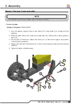
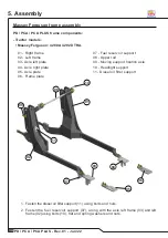
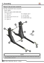
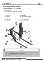
- Tractor models:

• Massey Ferguson: 4305 / 4306 / 4307.

13

13

12

12

06

06

01

01

08

08

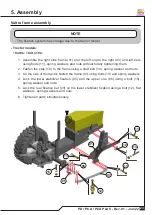
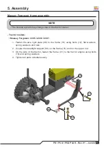
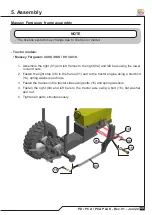
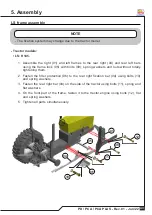
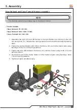
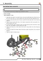
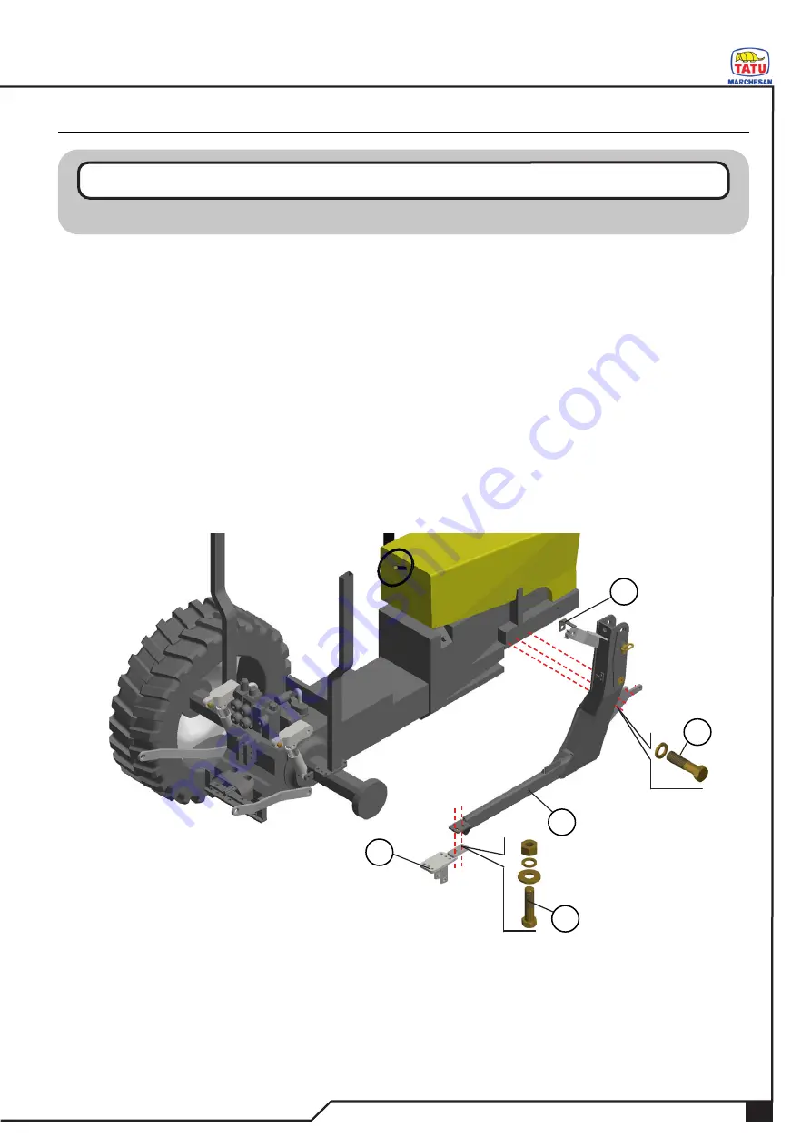
1.  Fasten the axle right plate (08) to the frame (01) using bolts (12), flat washers, 

spring washers and nuts.

2.  Couple the headlight support (06) on the frame (01) and on the upper rod.
3.  On the side of the tractor, fasten the frame (01) to the tractor engine using bolts 

(13) and spring washers.

4.  Tighten all parts simultaneously.

5. Assembly

Massey Ferguson frame assembly

- The fixation system may change due to the tractor model.

NOTE

Summary of Contents for PCA PLUS

Page 1: ...OPERATOR S MANUAL PD PCA PD PCA PCA PLUS PCA PLUS...

Page 2: ...Dealer Owner Firm Farm City State No of the Certificate of Guarantee Serial No Date Invoice No Product Notes IDENTIFICATION...

Page 3: ...must also read and understand the safety recommendations For any further explanation or in the case of technical problems that may arise during the service consult your dealer and the Technical suppo...

Page 4: ...lve 62 BT CDC JS LS circuit for tractor with closed center control valve 63 Circuit with flow divider for the tractor pump PCA 64 Circuit with control valve for the tractor pump PCA PLUS 65 Tatu hydra...

Page 5: ...ccessory hydraulic circuit 100 101 Flow divider valve DFE 102 SAB operational precautions PCA 103 Leveling rod 104 Self leveling system operational precautions SAE and PAC 104 Front loader correct use...

Page 6: ...nance of the equipment The instructions in this manual indicates how to get the best performance and allow the operator to get maximum income increasing the equipment lifetime This manual should be re...

Page 7: ...observed If the safety instructions are not being followed a serious accident or even death may occur Dear operator Respect the ecology Do not throw trash away This gesture of goodwill helps to protec...

Page 8: ...d treated seeds make any contact with your skin or clothes Keep access and work places clean or free from oil and grease Risk of accidents Never transport the equipment on highways or paved roads Avoi...

Page 9: ...ing support Have extreme caution when driving under electrical power lines Any contact may result in severe shocks injuries or death Do not open or remove the safety protections while the equipment is...

Page 10: ...ds and arms from the abrasive elements that may cause cuts or scratches Whenever assembling or elements that may cause cuts or scratches Whenever assembling or disassembling the equipment always use s...

Page 11: ...entangled to the moving parts of the equipment 8 Never operate the equipment without its protective devices 9 Have full knowledge of the soil before starting to work Use the speed which is suitable to...

Page 12: ...est that you carefully read the manual as it will be a guide for periodic verifications that need to be done and will allow that you assure the maintenance of your equipment 20 Fasten the safety chain...

Page 13: ...l overtaking and oncoming traffic 8 After 8 to 10 km transporting please inspect the load condition Repeat this procedure every 80 to 100 km Give more attention when transporting the equipment on roug...

Page 14: ...k Regulatory Standard NR 12 This Regulatory Standard and its annexes provide technical references basic principles and protective measures to ensure the health and physical integrity of workers and es...

Page 15: ...personnel should carry out the equipment movimentation Note every condition of each PPE such as the foot protection safety glasses safety helmet protective gloves and other PPE as required Use chains...

Page 16: ...ls The safety decals warn about the equipment points that require more attention and they should be kept in good repair If these decals become damaged or illegible replace them Marchesan provides deca...

Page 17: ...3 06 2659 01 PCA 800 AR decal 05 03 06 2769 01 PCA PLUS 1750 decal 05 03 06 2770 01 PCA 1100 AR decal 05 03 06 2916 01 PCA PLUS 2000 decal 05 03 06 2917 01 PD decal 05 03 06 2270 01 Special procedures...

Page 18: ...ck coupled to the tractor and without quick activation BT CD JS AR Tractor pump with double control valve with joystick and quick activation this system uses the same components as mentioned on the pr...

Page 19: ...AM weight kg 210 266 420 Detached weight kg 100 140 260 Bucket width mm 900 1200 1700 Normal load volume m 0 23 0 30 0 60 Over the border load volume m 0 30 0 40 0 75 Lifting height mm 2200 2250 2300...

Page 20: ...attachment 2200 600 235 LDA Dozer blade attachment 2400 600 285 LDA Dozer blade attachment 2600 600 295 GSA Agricultural silage fork 1640 0 75 345 GSA Agricultural silage fork 2290 1 05 430 EAG Refus...

Page 21: ...support 06 Stabilizer 02 Support bars 07 Lifting cylinder 03 Articulator 08 Articulator cylinder 04 Lever 09 Hydraulic circuit 05 Jack arm 10 Transport lock Check the accessories on the optional page...

Page 22: ...bars 08 Articulator cylinder 03 Articulator 09 Hydraulic circuit 04 Lever 10 Transport lock 05 Jack arm 11 Stabilizer arm 06 Stabilizer 12 Upper articulator 4 Components 11 11 11 11 02 02 12 12 07 07...

Page 23: ...lic circuit 03 Rods 08 Transport lock 04 High moving support guide 09 Exhaust extensor 05 Guide bar 10 Wrenches 11 Front blade optional For every tractor model there is a corresponding frame to it as...

Page 24: ...zer fixation 10 Stop PD PCA PCA PLUS frame components Tractor models Valtra 144 to 194 Valtra frame assembly 08 08 01 01 07 07 10 10 09 09 03 03 04 04 06 06 05 05 02 02 Only QUALIFIED and AUTHORIZED p...

Page 25: ...tightening them 2 Fasten the stop 10 to the frame using a stud bolt 14 spring washer and nuts 3 On the side of the tractor fasten the frame 01 using bolts 13 and spring washers 4 Lock the lower stabi...

Page 26: ...04 Stop 10 Lower rod 05 Frame shim 11 Moving support fixation axle 06 Central frame fixation outer shim 12 Exhaust extensor Valtra frame assembly If there is any exhaust extensor 12 it must be fastene...

Page 27: ...ter shim 06 to the frame 01 and to the tractor engine using bolts 18 and spring washers 4 On the side of the tractor between the frame 01 and the engine fasten the shim 05 using bolts 16 and spring wa...

Page 28: ...ion base 07 Front protection 07 07 09 09 08 08 03 03 04 04 10 10 12 12 09 09 13 13 11 11 02 02 05 05 06 06 01 01 PD PCA PCA PLUS frame components Tractor models Valtra A800R A850R A950R A990R Valtra f...

Page 29: ...s 3 Fasten the stud bolts 16 to the frame 01 using spring washers and nuts 4 Couple the front protection 07 to the front part of the frame using bolts 17 spring washers and nuts 5 Lock the rear fixati...

Page 30: ...tion axle 07 Left stop 5 Assembly PD PCA PCA PLUS frame components Tractor models Valtra A84 A94 A104 and A114 A124 A134 Massey Ferguson 4707 to 5710 and 6711 12 6713 Valtra and Massey Ferguson frames...

Page 31: ...r side between the frame 01 and tractor engine fasten the shim 14 using bolts 18 spring and flat washer 4 Couple the stop 07 on the front part of the frame tightening it to the tractor engine using bo...

Page 32: ...c turbine 07 must be fastened using the tractor original bolts NOTE 02 02 04 04 03 03 13 13 01 01 05 05 06 06 07 07 12 12 08 08 09 09 11 11 11 11 10 10 01 Right frame 08 Hydraulic turbine left protect...

Page 33: ...plate 09 on the frame 01 using bolts 15 flat washers spring washers and nuts 3 On the side of the tractor fasten the frame 01 to the tractor engine using bolts 16 and spring washers 4 Fasten the righ...

Page 34: ...l reservoir support 07 along with the axle left plate 03 and left frame 02 using bolts 10 flat and spring washers and nuts 09 09 08 08 01 01 07 07 02 02 03 03 03 03 02 02 07 07 05 05 06 06 04 04 01 Ri...

Page 35: ...01 using bolts 10 flat washers spring washers and nuts 3 On the side of the tractor fasten the frame 01 to the tractor engine using bolts 11 and spring washers 4 Tighten all parts simultaneously 5 Re...

Page 36: ...filter support 06 Frame plate 07 07 01 01 08 08 09 09 02 02 03 03 04 04 06 06 05 05 11 11 10 10 5 Assembly PD PCA PCA PLUS frame components Tractor models Massey Ferguson 4280 A 4292 XTRA Massey Fergu...

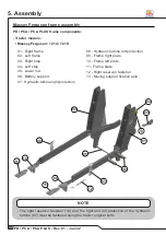
Page 37: ...ng bolts 12 flat washers spring washers and nuts 4 Couple the headlight support 10 on the frame 01 and on the upper rod 5 On the side of the tractor fasten the frame 01 to the tractor engine using bol...

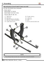
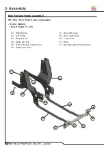
Page 38: ...eft plate 03 Moving support fixation axle 08 Axle right plate 04 Lower rod 09 Ladder fixation base 05 Upper rod PD PCA PCA PLUS frame components Tractor models Massey Ferguson 4305 4306 4307 Massey Fe...

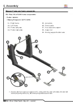
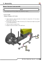
Page 39: ...g bolts 12 flat washers spring washers and nuts 2 Couple the headlight support 06 on the frame 01 and on the upper rod 3 On the side of the tractor fasten the frame 01 to the tractor engine using bolt...

Page 40: ...xtensor 01 01 02 02 06 06 05 05 04 04 03 03 09 09 10 10 07 07 08 08 12 12 11 11 5 Assembly PD PCA PCA PLUS frame components Tractor models Massey Ferguson 4408 08S 09 4410 Massey Ferguson frame assemb...

Page 41: ...Fasten the right stop 08 to the frame 01 and to the tractor engine using a stud bolt 14 spring washers and nuts 3 Fasten the frames on the tractor sides using bolts 15 and spring washers 4 Fasten the...

Page 42: ...pport 04 Plate 08 Greater bushing 5 Assembly PD PCA PCA PLUS frame components Tractor models LS 80 90 100 LS frame assembly The bushings are used if it is necessary to adjust the fixation If there is...

Page 43: ...he plate 04 on the rear fixation bar 03 using bolts 12 flat washers spring washers and nuts 3 On the side of the tractor fasten the frame 01 to the tractor engine using bolts 13 flat and spring washer...

Page 44: ...e lock 02 Left frame 06 Filter protection 03 Rear left bar 07 Upper rod 04 Rear right bar 08 Moving support fixation axle 02 02 01 01 05 05 03 03 07 07 08 08 04 04 06 06 PD PCA PCA PLUS frame componen...

Page 45: ...them 2 Fasten the filter protection 06 to the rear right fixation bar 04 using bolts 10 and spring washers 3 Fasten the rear right bar 04 on the side of the tractor using bolts 11 spring and flat was...

Page 46: ...09 Stop 05 Central fixation plate 10 Moving support fixation axle 5 Assembly PD PCA PCA PLUS frame components Tractor models New Holland 75 85 95 New Holland 5 80 5 90 5 100 Case Farmall 80 90 100 New...

Page 47: ...and nuts without totally tightening them 2 Fasten the central fixation shim 05 to the frame 01 and to the tractor side using bushings bolts 12 and spring washers 3 Fasten the stop 09 between the fram...

Page 48: ...cket 05 Frame fixation support bar 11 Smaller bracket 06 Frame right fixation support 12 Moving support fixation axle 5 Assembly PD PCA PCA PLUS frame components Tractor models New Holland 7630 New Ho...

Page 49: ...bolts 16 flat washers spring washers and nuts 3 Place the frame fixation support bar 05 on the right 04 and left 03 bars using bolts 14 flat washers spring washers and nut 4 On the side of the tracto...

Page 50: ...eft bar 09 Lower rod 04 Rear right bar 10 Stop 05 Frame fixation support bar 11 Moving support fixation axle 06 Rear plate shim 02 02 01 01 09 09 03 03 10 10 10 10 11 11 04 04 06 06 07 07 06 06 05 05...

Page 51: ...n support bar 05 using bolts 14 spring washers and nuts 4 Lock the fixation support bar 05 to the rear right bar 04 and to the left one using bolts 15 flat washers spring washers and nuts 5 Fasten the...

Page 52: ...Moving support fixation axle 02 Left frame 06 Left plate 03 Rear left bar 07 Right plate 04 Rear right bar 02 02 01 01 03 03 05 05 04 04 06 06 07 07 PD PCA PCA PLUS frame components Tractor models New...

Page 53: ...plate 07 to the rear right bar 04 using bolts 09 flat washers spring washers and nuts 3 Fasten the frame 01 to the tractor side using bolts 10 flat washers and spring washers 4 On the front part of th...

Page 54: ...n plate 12 Smaller bushing 06 Left plate 13 Moving support fixation axle 07 Frame upper plate 14 Left frame lock PD PCA PCA PLUS frame components Tractor models John Deere 5075 78 85 90 John Deere fra...

Page 55: ...using bolts 16 and flat washers 4 Place the fixation plate 05 on the right 09 and left bars using bolts 16 flat washers spring washers and nuts 5 Use the lock 14 on the frame 01 and on the tractor eng...

Page 56: ...07 Spacing bushing 04 Rear fixation left bar 08 Moving support fixation axle PD PCA PCA PLUS frame components Tractor models MHI 8000 9200 MHI 6075 8000S 9500S Mahindra frame assembly 5 Assembly 01 0...

Page 57: ...xation base 03 on the right 05 and left 04 bars using bolts 10 flat washers spring washers and nuts 3 On the side of the tractor fasten the bushing 07 between the frame 01 and the tractor engine using...

Page 58: ...aust 11 Diesel oil filter support 5 Assembly PD PCA PCA PLUS frame components Tractor models LDI 120 130 Landini frame assembly The bushings must be used when it is necessary to adjust the fixation If...

Page 59: ...one using bolts 12 spring washer and nuts without totally tightening them 2 Fasten the frame 01 to the tractor side using bolts 13 flat and spring washers 3 On the front part of the frame fasten it to...

Page 60: ...r support 05 Rear fixation right bar 5 Assembly PD PCA PCA PLUS frame components Tractor models LDI 145 175 Landini frame assembly 02 02 08 08 03 03 06 06 04 04 05 05 09 09 07 07 01 01 The bushings mu...

Page 61: ...and nuts without totally tightening them 2 Fasten the frame 01 on the tractor side using bolts 11 flat and spring washers 3 On the front part part of the frame fasten it to the tractor engine using b...

Page 62: ...ng a bolt flat washer spring washer and nut Plate fixation The plate and its fixation may change due to the tractor brand and model The plate D must be used when there are auxiliary cylinders and the...

Page 63: ...01 Jun 22 1 After assembling the right and left frames assemble the rod E and fasten it using nuts Rod assembly The axle threads E must be greased before their assembly Check the torque table page NO...

Page 64: ...Joystick Joystick P P RL RL R R Pressure Pressure Return Return Free return Free return Tractor Tractor rearview rearview For the tractor pump For the tractor pump Male quick Male quick coupler coupl...

Page 65: ...ale quick Male quick coupler coupler Female quick Female quick coupler coupler P P LS LS R R P P LS LS R R Pressure Pressure Return Return Load sense Load sense P P R R LS LS D D D D C C B B A A A A C...

Page 66: ...o the BT circuit Flow divider Flow divider P 1 P 1 P 1 P 1 P 2 P 2 P 1 P 1 P2 P2 R 1 R 1 R 1 R 1 R1 R1 R2 R2 R 2 R 2 R2 R2 R1 R1 R 2 R 2 P 2 P 2 P1 P1 P2 P2 Safety valve Safety valve detail detail 1 1...

Page 67: ...rt Moving support cylinder cylinder Accessories Accessories cylinder cylinder Safety valve Safety valve Control valve Control valve Safety valve Safety valve detail detail P1 P1 P1 P1 P1 P1 P2 P2 P2 P...

Page 68: ...rol valve PCA control valve P P Pressure Pressure P P RB RB RT RT Joystick Joystick PD control valve PD control valve Comes from the Comes from the moving support circuit moving support circuit A A D...

Page 69: ...Male quick Male quick coupler coupler Nipple fitting Nipple fitting P1 P1 R1 R1 R2 R2 P2 P2 Comes from the Comes from the moving support circuit moving support circuit A A B B A A B B 5 Assembly For...

Page 70: ...P P Safety valve Safety valve detail detail Moving support Moving support cylinder cylinder T oil distributor T oil distributor Safety valve Safety valve Male quick coupler Male quick coupler Female...

Page 71: ...ve Joystick Joystick P P RL RL R R Pressure Pressure Return Return Free return Free return RL RL Comes from the Comes from the circuit with PAH circuit with PAH Comes from the moving circuit Comes fro...

Page 72: ...BT complete system with control valve assembly The PCA assembly to the tractor must be done by a qualified person that works on the factory or on a reseller 1 First of all put all parts on a clean and...

Page 73: ...and nuts 5 Couple the control valve D to the base A using bolts D spring and flat washers BT tractor with control valve and quick coupler assembly The itens and the assembly may change due to the trac...

Page 74: ...trol valve input F to feed the control valve 8 On the lower part of the control valve fasten the pressure hose with return G that connects the control valve to the rear part of the tractor using an ad...

Page 75: ...to feed the control valve install the hoses for feeding the moving part of the front loader 1 Connect the hoses L to the control valve I to the frame M and to the male couplers I I M M L L 5 Assembly...

Page 76: ...and on a sequence to facilitate the wrench handling 3 Couple the female multiconnector I to the control valve J and lock using a lock lever Double control valve Double control valve with pressure pas...

Page 77: ...ks on the factory or on a reseller 1 First of all put all parts on a clean and easy to identify place 2 Check the amounts on the list that can be found inside the box 1 Remove the front counterweights...

Page 78: ...nspect the sealing rings on the quick couplers Replace them if there is any leakage 3 Before coupling the equipment hoses clean the quick coupler surface 4 The hoses coupling is done by pushing the qu...

Page 79: ...ts position 1 Remove the front counterweights A For some tractor brands or models it is necessary to also remove the front support B The support and counterweights may change due to the tractor brand...

Page 80: ...or brand or model it is necessary to remove or change positions of some items that may prevent the frame fixation to the tractor such as side protections glass fenders batteries battery supports ladde...

Page 81: ...Hitching to the tractor 5 Activate the control valve levers until the cylinders reach their final course Check if there is any leak 6 Fill up the oil reservoir and check the Minimum and Maximum indica...

Page 82: ...nt it is necessary to slightly activate the control valve lever to facilitate the unhitching NOTE Never mix different brands of oil Never pour oil above the level NOTE 3 Shut down the engine and activ...

Page 83: ...frames 2 Couple the right C and left D hydraulic cylinders using a pin E hexagonal washer and nut Front loader moving support assembly The hydraulic cylinder connections must be positioned facing the...

Page 84: ...ing support A locking with pins D C C B B A A D D 3 3 2 2 1 1 5 Assembly 3 When the equipment is operating with the blade use the side holes 1 and 3 to give a right or left angle on the blade 4 When t...

Page 85: ...ight and left frames using bolts E and spring washer lock the other end of the bars on the moving support A using bolts F spring washers and nuts 3 Lock the supports B on the right and left frames usi...

Page 86: ...altra PD Valtra 154 174 180 194 154 174 180 194 PD Valtra PD Valtra A114 A124 A134 A114 A124 A134 PD MF PD MF 4275 4290 4275 4290 PD MF PD MF 6711 6712 6713 6711 6712 6713 PD Valtra PD Valtra A84 A94...

Page 87: ...01 Jun 22 PD MF PD MF 4707A5710 4707A5710 PD MF PD MF 7214 7219 7214 7219 PD NH PD NH 7630 4 7630 4 PD NH PD NH 75 85 95 75 85 95 PD JD PD JD 5075 78 85 90 5075 78 85 90 Front loader support guide fix...

Page 88: ...B flat and spring washers 2 It is required to make the holes to fasten the joystick If the platform does not have the holes to pass the joystick cables create holes with 35 mm of diameter Choose a pl...

Page 89: ...leave the factory with a welded reservoir support 2 Lock the reservoir D on the support A using bolts E spring and flat washers 3 Remove the return filter F and place the pipe fitting G on the reserv...

Page 90: ...n hose E on the reservoir duct and and the pump duct using curved connectors or clamps passing it through the side support E E B B D D A A C C G G I I H H F F 5 Assembly 3 Lock the pressure hose F on...

Page 91: ...structions 1 Support the PCA on a flat and firm place A A Only CAPABLE and AUTHORIZED personnel must carry out the adjustments and operations of the equipment Observe every safety condition and use sa...

Page 92: ...and holes free the lever B so that the pins C get in position and the optional parts are hitched On this operation it may be necessary to activate the front cylinder to facilitate hitching the pins 5...

Page 93: ...oth sides If necessary adjust the gauge 2 If it is necessary change the turning radius of the front axle by the adjusting bolt A and nut The bolt A adjustment must allow a total articulation of the fr...

Page 94: ...e hydraulic circuit must be on an spot that facilitates the visualization NOTE A A 6 Adjustments and operations 1 Couple the gauge A on the front hose of the right cylinder and activate it to lower th...

Page 95: ...orward or backward will move the support and a movement to the right or to the left will tilt the agricultural bucket The button A will only work if the used accessory has a third function as is the c...

Page 96: ...not designed to clean the field for plantation 10 If the equipment has the agricultural silage fork remove the hay from the top to the bottom by moving the cylinder until the material is released 11 D...

Page 97: ...CA PLUS Rev 01 Jun 22 7 Optional PCA accessories The PCA leaves the factory without accessories NOTE LDA 2400 LDA 2400 LDA 2600 LDA 2600 PAC PAC LDA 2200 LDA 2200 EAG EAG SAE SAE SAB SAB GRF GRF GCA G...

Page 98: ...96 PD PCA PCA PLUS Rev 01 Jun 22 PD accessories SAB SAB PAH PAH PAM PAM DE DE 7 Optional...

Page 99: ...tick will return to neutral as the oil that was feeding the circuit of this movement will be going to feed the third function circuit of your accessory 3 After releasing the button the third function...

Page 100: ...ic circuit for the operation of the following accessories agricultural silage fork GSA agricultural loader fork GCA and the hay claw GRF Joystick Joystick Battery Battery Flow divider Flow divider Con...

Page 101: ...2 3 3 Flow divider For each tractor brand and model the hydraulic circuit assembly may suffer variations on the connection ports and on the hoses length Keep the same connection order between the pre...

Page 102: ...nd if they are properly installed IMPORTANT Pressure Return Accessory hoses until the flow divider valve Oil duct Male quick coupler 1 2 NPT with cap Hydraulic cylinder 1 1 A A B B P P R R C C 1 1 R R...

Page 103: ...ead sealing tape to couple the male quick coupler to the hoses During maintenance or replacement avoid that the ports touch the soil When the hydraulic hoses assembly is done carry out a general inspe...

Page 104: ...102 PD PCA PCA PLUS Rev 01 Jun 22 Flow divider valve fixation DFE Couple the flow divider valve A to the fixation base B on the lower part of the front loader C using bolts D B B A A C C D 7 Optional...

Page 105: ...close to the ground to avoid that the tractor tip over 2 When lifting the sack to fill up trailers or planters make sure to be over a flat place 3 Do not spread the support as the more the sack is far...

Page 106: ...lping the operator to control the load during operation This system keeps the load on the same position when it is being lifted Therefore it is not necessary to make angle compensations since the stru...

Page 107: ...105 PD PCA PCA PLUS Rev 01 Jun 22 Front loader correct use Correct Correct Incorrect Incorrect 7 Optional...

Page 108: ...the tractor tip over Correct way to use the equipment Correct Correct Incorrect Incorrect Avoid to use the front traction when working with the front loader as this act may cause damages to the struct...

Page 109: ...107 PD PCA PCA PLUS Rev 01 Jun 22 GSA Correct way to use the equipment Correct Correct Incorrect Incorrect 7 Optional...

Page 110: ...LUS Rev 01 Jun 22 Front loader angular adjustment The front loader has the option to adjust the working angle of the accessory as the front loader either on a horizontal or on a vertical position 20 2...

Page 111: ...109 PD PCA PCA PLUS Rev 01 Jun 22 Front loader cutting depth adjustment To adjust the blade cutting depth loosen up the bolts A and nut that lock the plates B A B PCA PCA PD PD B A 7 Optional...

Page 112: ...n valve E on the SAB cylinder and on the female quick coupler locked on the moving support 4 The extension F must be positioned as shown on the illustration below This equipment has a lifting cylinder...

Page 113: ...free to work without the risk of accidents B A Only QUALIFIED CAPABLE and AUTHORIZED personnel must carry out the maintenance of the equipment Every maintenance must follow the recommendations that a...

Page 114: ...carry out a proper lubrication as indicated below a Every 10 working hours lubricate the articulations through the grease fittings as follows 1 Be sure about the lubricant quality regarding the effic...

Page 115: ...113 PD PCA PCA PLUS Rev 01 Jun 22 Lubricate the points shown above and all grease fittings as well ATTENTION Lubrication points Lubricate every 10 working hours 8 Maintenance...

Page 116: ...114 PD PCA PCA PLUS Rev 01 Jun 22 Lubrication points Lubricate every 10 working hours 8 Maintenance Lubricate the points shown above and all grease fittings as well ATTENTION...

Page 117: ...voir again using the parts described above 4 Always use oil 68 with comproved quality and that follows the ISO VG 68 standard Never mix different brands of oil Never pour oil above the level NOTE A B...

Page 118: ...plug again and fill up the reservoir using ISO VG 68 hydraulic oil 3 Reservoir capacity 50 liters check the lever by the indicator on the dipstick B 4 The oil level must be checked daily being the cy...

Page 119: ...ry for cleaning including the nearby areas to avoid that any impurity get inside the filter 3 To finish the cleaning it is indicated to use a cloth 4 Place the sealing accessory and the new filter tha...

Page 120: ...le of minutes keeping a slow gear 3 Increase the engine up to 1300 rpm revolutions per minute and activate the control valve lever from the neutral position to the two ends alternately so that the cyl...

Page 121: ...Make sure you have the correct tools for the job You may require the following tools Proper seal kit Screwdriver and rubber cable Pliers and wrenches Ports Ports Disassembly 1 Remove the end cap A 2...

Page 122: ...E and end cap A 2 Secure piston C to rod with lock nut D Torque lock nut to proper value consult torque table on the important data section 3 Lube inside of barrel piston seals and gland seals with hy...

Page 123: ...er problems consequently leading to internal leakages lack of power gripping damages to the cylinder rods etc Do not attempt any makeshift repairs to the hydraulic lines fittings or hoses by using tap...

Page 124: ...y showing a lack of power Low oil level Fill up the reservoir to the level Hydraulic cylinder with inner leaks Test the equipment using another hydraulic system If the problem persists check replace t...

Page 125: ...d hoses Assemble the hoses correctly Hydraulic cylinder leaking Damaged cylinder Replace the cylinder Damaged rod Replace the rod Oil with impurities Replace the oil repairings and filtering elements...

Page 126: ...k wear occurence on all moving parts Replace any part if necessary Always use eye protection when operating the equipment Replace the missing or damaged safety decals Marchesan supplies these decals u...

Page 127: ...6 455 616 3 4 10 167 226 5 269 5 365 4 380 5 516 0 M 18 x 1 5 96 5 130 854 257 348 49 378 512 568 3 4 16 186 252 2 300 406 8 424 5 575 6 M 20 x 2 5 121 5 164 754 323 5 438 67 475 644 1 7 8 9 169 5 229...

Page 128: ...y equipment or parts at any time without thereby becoming liable to make similar changes in machinery equipment or parts previously sold Images are for illustration purposes only Some illustrations in...

Page 129: ...trabajo 11 No efectuar regulajes con el equipo en funcionamiento 12 No permitir que ni os jueguen sobre o pr ximo de los equipos en operaci n durante el transporte o almacenado 13 La velocidad de ope...

Page 130: ...www marchesan com br...

Reviews: