background image


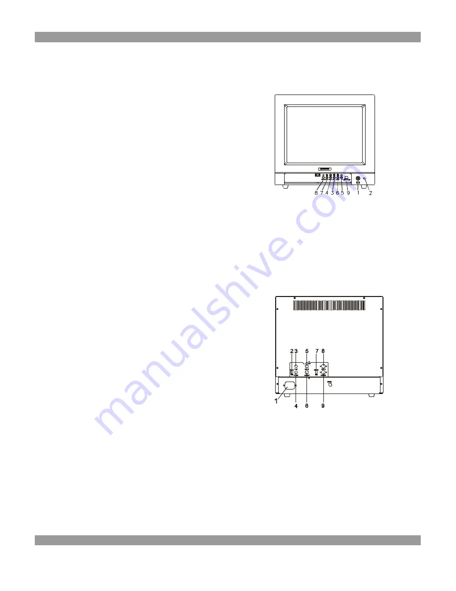
TCM-1402S MONITOR FRONT AND REAR VIEW


Front View 


1. Power On/Off Switch 

2. Power-On Indicator 

3. Contrast Adjustment 

4. Brightness Adjustment 

5. Tint Adjustment 

6. Color Adjustment 

7. Sharpness Adjustment 

8. Volume Adjustment 

9. CVBS1 / S-Y/C Select Switch 


 TCM-1402S 


Rear View 


1. Power Inlet 

2. Video Load Impedance Switch 

3. Video 1 Input : BNC Connector 

4. Video 1 Output : BNC Connector 

5. Audio 1 Input : RCA Jack 

6. Audio 1 Output : RCA Jack 

7. S-Y/C Load Impedance Switch 

8. S-Y/C Input Connector 

9. S-Y/C Output Connector 


 TCM-1402S 


Summary of Contents for TCM-0902

Page 1: ...Operating Instructions For Color Video Monitor TCM 0902 TCM 1001 TCM 1002S TCM 1402S TCM 1501 TCM 1701 TCM 1901 TCM 2102S TATUNG Company Of America...

Page 2: ......

Page 3: ...d Rear Views 6 6 TCM 1002S Monitor Front and Rear Views 7 7 TCM 1402S Monitor Front and Rear Views 8 8 TSCM 1501 HI RES Monitor Front and Rear Views 9 9 TCM 1701 HI RES Monitor Front and Rear Views 10...

Page 4: ...into an outlet on a circuit different from that to which the receiver is connected Consult the dealer or an experienced radio TV technician for help Shielded interface cables and A C power cord if an...

Page 5: ...plug the unit immediately and notify the service technician A If liquid has been spilled into the display or the display has been exposed to rain or water B If the unit has been dropped or the cabinet...

Page 6: ...s 50 Hz 3 Video Input Signal CVBS1 CVBS2 S Y C 4 Audio Input Signal AU1 AU2 5 Input Power 100 240V AC 6 Limited twelve months warranty STANDARD SYSTEM COMPONENTS AND ATTACHMENTS The various components...

Page 7: ...Color Adjustment 7 Sharpness Adjustment 8 Volume Adjustment 9 CVBS1 CVBS2 S Y C Select Switch TCM 0902 Rear View 1 Power Inlet 2 Video 1 Input BNC Connector 3 Video 1 Output BNC Connector 4 Video 2 I...

Page 8: ...TCM 1001 Rear View 1 Power Inlet 2 Video 1 Video 2 Select Switch 3 Video Load Impedance Switch 4 Video 1 Input BNC Connector 5 Video 1 Output BNC Connector 6 Video 2 Input BNC Connector 7 Video 2 Out...

Page 9: ...t 6 Color Adjustment 7 Sharpness Adjustment 8 Volume Adjustment 9 CVBS1 S Y C Select Switch TCM 1002S Rear View 1 Power Inlet 2 Video Load Impedance Switch 3 Video 1 Input BNC Connector 4 Video 1 Outp...

Page 10: ...t 6 Color Adjustment 7 Sharpness Adjustment 8 Volume Adjustment 9 CVBS1 S Y C Select Switch TCM 1402S Rear View 1 Power Inlet 2 Video Load Impedance Switch 3 Video 1 Input BNC Connector 4 Video 1 Outp...

Page 11: ...ch 10 Audio 1 Audio 2 Select Switch TCM 1501 Rear View 1 Power Inlet 2 Video 1 Load Impedance Switch 3 Video 2 Load Impedance Switch 4 Video 1 Input BNC Connector 5 Video 1 Output BNC Connector 6 Vide...

Page 12: ...tch 10 Audio 1 Audio 2 Select Switch TCM 1701 Rear View 1 Power Inlet 2 Video 1 Load Impedance Switch 3 Video 2 Load Impedance Switch 4 Video 1 Input BNC Connector 5 Video 1 Output BNC Connector 6 Vid...

Page 13: ...tch 10 Audio 1 Audio 2 Select Switch TCM 1901 Rear View 1 Power Inlet 2 Video 1 Load Impedance Switch 3 Video 2 Load Impedance Switch 4 Video 1 Input BNC Connector 5 Video 1 Output BNC Connector 6 Vid...

Page 14: ...ect Switch 11 Underscan Select Switch 12 16 9 Select Switch TCM 2102S Rear View 1 Power Inlet 2 Video 1 Load Impedance Switch 3 Video 2 Load Impedance Switch 4 Video 1 Input BNC Connector 5 Video 1 Ou...

Page 15: ...o video in RCA BNC connectors of the monitor 5 Turn your device system power switch ON then turn the monitor power switch ON The power indicator will be ON at this moment 6 Allow about 30 seconds for...

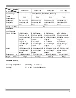
Page 16: ...n 300 lines Y C more than 350 lines 300 lines Y C more than 350 lines 350 lines Y C more than 450 lines 400 lines Y C more than 450 lines Sweep Linearity 10 GENERAL Input Output Video S Video 2 BNC in...

Page 17: ...gh output 2 BNC inputs 75ohms or Hi Z 2 looping through outputs 1 input DIN 1 loop through output 2 BNC inputs 75ohms or Hi Z 2 looping through outputs 1 input DIN 1 loop through output 2 BNC inputs 7...

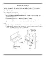
Page 18: ...racket FIG 1 by using the screws and adapter bars provided in the package 3 Secure the brackets directly to the rack frame see FIG 2 below Warning At least two persons are necessary to place the monit...

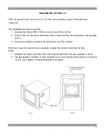
Page 19: ...side of the monitor with the screw provided in the package FIG 1 3 Secure the brackets directly to the rack frame see FIG 2 below Warning At least two persons are necessary to place the monitor mount...

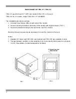
Page 20: ...re mounting brackets to both side of the monitor with original screws FIG 1 3 Secure the brackets directly to the rack frame see FIG 2 below Warning At least two persons are necessary to mount the mon...

Page 21: ...TATUNG COMPANY OF AMERICA 2850 EL PRESIDIO ST LONG BEACH CA90810 800 827 2850 3121 0266 09...

Reviews: