11
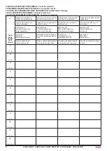
ARM200 Series
A
R
M
2
7
0
X°
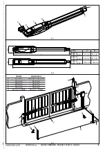
A (mm)
B (mm)
C (mm)
90
80 ÷ 235
120 ÷ 300
20 mm
90
240
120 ÷ 295
20 mm
90
245
120 ÷ 290
20 mm
90
250
120 ÷ 285
20 mm
100
130 ÷ 195
120 ÷ 300
20 mm
100
200
120 ÷ 295
20 mm
100
205
120 ÷ 290
20 mm
100
210
120 ÷ 285
20 mm
100
215
120 ÷ 280
20 mm
100
220
120 ÷ 275
20 mm
100
225
120 ÷ 270
20 mm
100
230
120 ÷ 265
20 mm
100
235
120 ÷ 260
20 mm
100
240
120 ÷ 255
20 mm
100
245
120 ÷ 250
20 mm
100
250
120 ÷ 245
20 mm
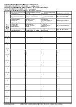
When measurement “C” is greater/smaller than 20 mm, increase/
diminish measurement “B” by the difference (e.g.: if C= 25mm,
increase “B” by 5mm), making sure that it does not exceed the
limits shown in the table.
If the pillar dimensions or the hinge position do not allow the
installation of the actuator, a niche on the pillar, as shown in Fig.
5, should be created in order to maintain the A dimension as
determined. The niche should be dimensioned in such a way to
enable easy installation, actuator rotation and operation of the
release device. The mounting brackets are designed to enable
small adjustments in both directions (fig.5A). In any case, always
refer to the measurements shown in the table.
Please keep to the values given in the table and oil the gate’s
hinges.
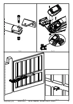
1_ Fix the rear bracket in the position determined before. In the
event of iron pillar carefully use n°4 Ø 6,3 mm self-drilling screw
(fig.6). In the event of brick pillar (fig.7), use n°4 M8 bolts (after
you have assembled it, fig.7A).
During the fastening operations, check if the bracket is
perfectly horizontal by means of a level.
2_ Set the operator for manual operation (see paragraph
MANUAL
RELEASE).
3_ Completely extend the rod till it reaches the limit stop (1 fig.8).
4_ Lock the operator again (see paragraph
RESTORING NORMAL
OPERATION).
5_ Turn the rod clockwise half a revolution (2 fig.8).
6_ Assemble the front bracket as shown in fig.9. Fasten the screw
using the special nut (fig.9).
7_ After removing the terminal board cover, anchor the actuator
to the rear bracket using the screw and nut supplied (see 1
fig.10);
ATTENTION: The actuator can be moved by hand only if
it is installed on the gate and in released position (see
paragraph MANUAL RELEASE).
ATTENTION: carefully verify that, when gate is
closed, the actuator’s rear do not touch the bracket
(see fig. 10). If so adjust the setting accordingly.
8_ Check measurement “L” according to the table (fig.4).
9_ rest the bracket that has just been fixed, onto the wing of the
completely closed gate and mark the fixing points (make sure it
is level, see fig. 11).
Before going on to the next phase please carry out the following
test:
10_ Release the actuator (see paragraph
MANUAL RELEASE
)
and manually check if the gate can completely open without
hindrances and stop at the mechanical travel stops as well as
if the leaf moves regularly without any friction.
11_ Carry out the necessary corrective measures and repeat from
point 10. Manually open the gate to the maximum required
angle;
12_ Tighten the arm until the front bracket finds itself over the
position just marked on the gate.
If the small bracket does cover the position marked it means
installation has been done correctly.
This method can be used to establish where the small bracket will
have to be welded for each opening angle (X°) required provided
it is possible (parameters A and B and the actuator’s useful travel
permitting).
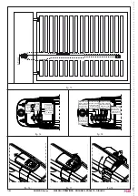
13_ fasten the gate mounting bracket in the position indicated
(fig.12), referring to the dimensions shown in fig. 13 and
ensuring the planarity of the assembly.
Note: if the gate structure does not allow a fix
bracket fastening it is necessary to create a sturdy
supporting base in the gate structure.
Note: for complete safety, the mechanical stops with
rubber cap (floor stops) must be fitted in opening
and closing of the gate (7 fig.3), in order that they
intervene just before the mechanical piston stops.
WIRING THE ACTUATOR
A terminal board is fitted in the lower part of the actuator for the
connection of the motor, of any limit switch and for the earthing of
the actuator. (figg.14-15).
Connect the motor and the earthing with reference to fig.14-15 and
to the table.
ARM200 - 230 Vac
POS.
COLOR
DESCRIPTION
1
Blue
Common cable
2
Brown
Phase 1
3
Black
Phase 2
T
Yellow / Green
Earthing
Connect up the condenser in parallel to the 2 phases of the motor
(terminals 2 and 3). Warning! Do not short-circuit the two wires as
this may cause discharges because of the current remaining in the
wires. Use control units with torque limiting device only.
ARM200BENC - 12 Vdc
POS.
COLOR
DESCRIPTION
1
White
Encoder signal
2
Blue
Encoder negative
3
Brown
Encoder positive
4
Blue
Motor neutral
5
Red
Motor phase
Only use control units fitted with an electric clutch.
TAU srl recommends its composite cable, Code
M-03000010CO;
START-UP
ATTENTION: Cut power before any job on the
system or on the actuator.
Carefully observe points 10, 11, 12, 13 and 14 of the SAFETY
GENERAL RULES.
With reference to the indications in fig.3 and in the table (see
paragraph
INSTALLATION)
, set the ducts and carry out the
electrical connections of the control board and of the chosen
accessories.
Choose short routes for cables and keep power cables separate
from control cables.
1) Power the system and check the status of the LED’s according
to the control unit instructions.
2) Program the control board according to the needs by following
the given instructions.
ENGLISH


