background image

SECIFICATION

l

  SYSTEM                        PAL/SECAM,B/G,I,NICAM/A2

l

  POWER INPUT                  AC 170-245V(50/60Hz)

l

  POWER CONSUMPTION          85W

l

  AERIAL IMPEDANCE            75OHM UNVALANCED

l

  TUNER                         VOLTAGE SYNTHESIZER TUNING

l

  RECEIVING CHANNELS          VHF-L E2-S6

                                   VHF-H S7-S41
                                   UHF E21-E69

l

  PROGRAMME                   MAX.99 PROGRAM MEMORIES

l

  PICTURE TUBE                  25”,28”,110

l

  SOUND OUTPUT                 3.0W X2

l

  SPEAKER                       8W 8 OHM X2

l

  AV JACKS                       FULL SCART  2

CAUTION: Before servicing the chassis, read the “Safely Precaution”.
“X -Ray radiation Precaution” and “Product Safety Notice” in this manual.

X-RAY RADIATION PRECAUTION

1. Excessive high voltage can produce potentially hazardous X-RAY

RADIATION. To Avoid such hazards the high voltage must be specified
limit. The normal value of the high voltage of this receiver is 26.5KV +/-
2KV under 230V AC power source. The high voltage must not exceed
29KV.

2. Each time a receiver requires servicing the high voltage should be

checked following the HIGH VOLTAGE CHECK procedure in this manual.
It is recommended the reading of the high voltage be recorded as a part
of the service record. It is important to use an accurate and reliable high
voltage meter.

3. The primary source of X -RAY RADIATION in this TV receiver is the

picture tube. For continued X-RAY RADIATION protection, the
replacement tube must be exactly the same type tube as used in this TV
receiver.

4. Some parts in this receiver have special safety-related characteristics for

X-RAY RADIATION protection. For continued safety, parts replacement
should be undertaken only after referring the PRODUCT SAFETY
NOTICE below.

SAFETY PRECAUTION

WARNING: Service should not be attempted by anyone unfamiliar with the
necessary Precautions on this receiver.
The following are the necessary precautions to be observed before

Summary of Contents for TV4KF-NICAM/A2/TXT

Page 1: ...TV4KF NICAM A2 TXT SERVICE MANUAL COLOUR TETELEVISION ...

Page 2: ...rce The high voltage must not exceed 29KV 2 Each time a receiver requires servicing the high voltage should be checked following the HIGH VOLTAGE CHECK procedure in this manual It is recommended the reading of the high voltage be recorded as a part of the service record It is important to use an accurate and reliable high voltage meter 3 The primary source of X RAY RADIATION in this TV receiver is...

Page 3: ...trical and mechanical parts in this chassis have special safety related characteristics are often passed unnoticed by a visual inspection and the X RAY RADIATON protection afforded by them cannot necessarily be obtained by using replacement components rated for higher voltage The use of substitute replacement parts that do not have the same safety characteristics as specified in the parts list may...

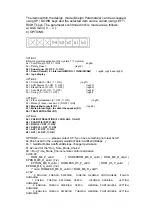
Page 4: ...ing OK key Service 2 is accessed by pressing Enter key again Service 3 and Service 4 is accessed By pressing PP key we come out of Service mode The items within the Service 1 mode can be accessed using UP DOWN keys and the selected item can be varied using LEFT RIGHT keys The parameters controlled in the Service 1 menu are a Red Gain 0 63 b DC Red 0 63 c Green Gain 0 63 d DC Green 0 63 e Blue Gain...

Page 5: ...d adjust VCO Coarse L1 and VCO Fine L1 to get VCO OK Status If the cursor is in VCO Coarse L1 or Fine L1 and the display shows VCO OK status then pressing of MENU key will automatically put VCO fine for L1 to the Centre of the 60 to 60 KHz window When in Service 2 menu if OK key is pressed Service 3 menu appears and the display is as follows The parameters controlled in the Service 3 menu are a V ...

Page 6: ... Mute pin low high to contol the speaker 0 1 b0 TDA7449 TDA7439 0 1 OPTION4 b5 VHF UHF SELECTION 0 VHF UHF 1 UHF b4 SCART2 0 OFF 1 ON b3 RGB 0 OFF 1 ON b2 SVHS 0 OFF 1 ON b1 AV2 0 OFF 1 ON b0 AV1 0 OFF 1 ON OPTION5 please contact ST if you have something not clear here b4 b5 b6 used for the autogain GainDacTable Adoffset ADslope b3 GainDacTable Adoffset ADslope changed permission b1 b2 used for th...

Page 7: ...service command 1 PP exit 2 OK switch between the service menu 3 AV auto VCO adjust 4 MUTE one line gain 5 ANALOG sub brightness adjust The AV2 should not be set while the RGB is set on ...

Page 8: ...1 5 9 6 7 8 ñ ò 2 3 4 ...

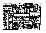
Page 9: ...31 18n C429 100n C425 22n C424 100n C423 100n C428 100n C427 18n C426 5 6n C422 22n C421 5 6n R421 2 7K C435 10u RIN1 RIN2 LIN1 LIN2 C444 4 7uF C439 4 7uF C3406 0 1u C3420 0 1u C003 4n7 C012 0 1u C005 220n C004 220P OSD B OSD G OSD R OSD FB SDA SCL C021 82P C019 470n C036 22P R039 5K6 C035 4n7 C022 104 C033 0 1u 5V 5V OUT GND VCC IC011 C040 0 1u 5V CVBS OUT2 VS 1 SC VT 33V SW6 P SW5 P SW4 V SW3 V ...

Reviews: