background image

6

12L

11

12L

12L

12R

11

6

step3

6

x2

a

b

M8*1.25*20L

x

4

14

FX10.5

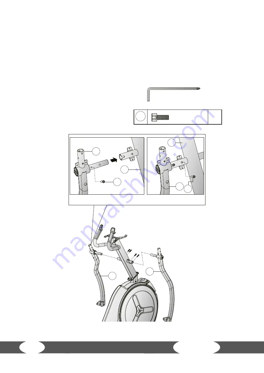
Step 3:

 Mounting the arms

1.  Screw the left arm (12L) onto the console mast (11) with two Allen screws (6).
2.  Screw the right arm (12R) onto the console mast (11) with two Allen screws (6). Only hand 

tighten the screws in place.

Summary of Contents for Crosstrainer FX10.5 Pro

Page 1: ...TFFX105 01 03 max 180 kg 90 Min C M 127 kg Crosstrainer FX10 5 Pro Assembly and Operating Instructions L 211 W 82 H 188 Art No TF FX105 ...

Page 2: ...2 FX10 5 ...

Page 3: ...er Straße 55 24837 Schleswig Germany Management Christian Grau Sebastian Campmann Dr Bernhard Schenkel No HRB 1000 SL Local Court Flensburg European VAT Number DE813211547 Disclaimer 2011 Taurus is a registered brand of the company Sport Tiedje GmbH All rights reserved Any use of this trademark without the explicit written permission of Sport Tiedje is prohibited Product and manual are subject to ...

Page 4: ...follow the instructions and that all parts are securely in place If required read through the instructions again to correct any mistakes Please pay close attention to the safety and maintenance instructions given here The contract partner cannot be held liable for damage to health accidents or damage to the equipment when it is not used in accordance with these instructions The following safety in...

Page 5: ... Quick Start program 24 3 5 2 Target programs 24 3 6 PROGRAM Profile programs 25 3 7 USER User defined program 27 3 8 H R C Heart rate controlled programs 28 3 9 WATT Watt program 29 3 10 RECOVERY Recovery function 29 3 11 BODY FAT Body fat analysis 30 3 12 Bluetooth and fitness apps 31 4 STORAGE AND TRANSPORT 32 4 1 General Instructions 32 4 2 Transportation Wheels 32 5 TROUBLESHOOTING CARE AND M...

Page 6: ...6 FX10 5 7 RECOMMENDED ACCESSORIES 36 8 ORDERING SPARE PARTS 37 8 1 Serial Number and Model Name 37 8 2 Parts List 38 8 3 Exploded Drawing 43 9 WARRANTY 44 10 CONTACT 46 ...

Page 7: ...M 50 400 W Min and max Watt at 100 RPM 148 765W User profiles 4 Programs in total 23 Quick start program 1 Target programs 4 Pre set programs 12 User defined programs 1 Heart rate programs 4 Watt programs 1 Recovery test 1 Body fat test 1 Stride length max 56 cm Stride height 14 cm Transfer ratio 1 8 75 Flywheel mass 10 kg Weight and dimensions Packed dimensiosn LxBxH 125 cm x 65 cm x 95 cm Assemb...

Page 8: ...ccess to the equipment Persons with disabilities must have a medical license and must be under strict observation when using the equipment The equipment is strictly for use by one person at a time If your equipment provides a safety key the clip of the safety key must be attached to your clothing before starting your training In the event of a fall the EMERGENCY STOP of the equipment can be initia...

Page 9: ...inimum fuse rating of 16 A slow blow Do not make any changes to the mains cable or the mains plug Keep the mains cable away from water heat oil and sharp edges Do not route the mains cable underneath the equipment or under a carpet or rug and do not place any objects on top of it 1 4 Set Up Place WARNING Do not place the equipment in main corridors or escape routes CAUTION The training room should...

Page 10: ...TION Do not open the packaging when it is lying on its side Ensure to have sufficient room for movement in each direction during assembly The assembly of the equipment must be carried out by at least two adults If in doubt seek the help of a third technically skilled person ATTENTION To prevent damage to the equipment and the floor assemble the equipment on a mat or packaging board L NOTICE In ord...

Page 11: ...6PCS 8 9 10 M12 1 75 70L 4PCS 72 M12 1 75 12T 4PCS 6 74 D24 D13 5 D2 5T 8PCS 73 M6 1 0 15L 8PCS M5 0 8 12L 8PCS 97 M5 0 8 12L 10PCS 97 M8 1 25 25L 4PCS 119 D15 4 D8 2 2T 4PCS 4 D16 D8 5 1 2T 4PCS 7 KH 747A2 128 ST4 2 15L 2PCS 96 11 2 2 Scope of Delivery The scope of delivery consist of the following parts At the beginning check whether all parts and tools belonging to the device are included in th...

Page 12: ... together and check that they fit properly Tighten the screws using the tool only when you are instructed to do so Step 1 Assembling the front and rear feet 1 Screw the frontal foot 2 to the main frame 1 with two hexagonal screws 3 two hexagonal screws 5 and four spring washers 4 Only hand tighten the screws in place 2 Connect the incline cable 158 and the control cable 167 together 3 Connect both...

Page 13: ...le in the mast 101 with the console cable in the main frame 102 2 Connect the signal cable in the mast 178 with the signal cable in the main frame 179 ATTENTION In the following step please pay attention that you don t clamp the cables between the frames 3 Screw the console mast 11 to the main frame 1 with four washers 7 four spring washers 4 four screws 119 and hand tighten the screws in place 4 ...

Page 14: ... b M8 1 25 20L x4 14 FX10 5 Step 3 Mounting the arms 1 Screw the left arm 12L onto the console mast 11 with two Allen screws 6 2 Screw the right arm 12R onto the console mast 11 with two Allen screws 6 Only hand tighten the screws in place ...

Page 15: ...ep 4 Mounting the pedals 1 Mount the right and left pedal poles 14R 14L on their respective sides of the main frame 1 each with two washers 73 one Allen screw 72 and one locking nut 74 see fig 4 1 2 Mount the right and left pedal mounts 15R 15L on their repsective arm 12R 12L each with two washers 73 one Allen screw 72 and one locking nut 74 see fig 4 2 3 Mount the right and left pedals 44 onto th...

Page 16: ... 9 10 5 2 5 1 10 9 8 step5 16 FX10 5 Step 5 Mounting the handles Screw the right and left handles 13R 13L onto the respecitve arm 12R 12L each with three curved washers 9 three Allen screws 8 and three locking nuts 10 see figs 5 1 5 2 Only hand tighten the screws in place ...

Page 17: ...d the second hot key cable from the console 107 with the second hot key cable from the console mast 109 see fig 6 1 3 Connect the signal cable from the console 177 with the signal cable from the console mast 178 see fig 6 1 ATTENTION In the following step please pay attention that you don t clamp the cables between the frames 4 Screw the console 19 onto the console mast 11 with four screws 97 see ...

Page 18: ...ver 64 and screw it onto the arms 12R 12L each with one screw 96 see fig 7 3 5 Screw the left protective cover 30L onto the main frame 1 with two screws 96 and one screw 97 and hand tighten the screws in place 6 Clip the right protective cover 30R onto the left protective cover 30L and screw it onto the main frame 1 with one screw 97 see fig 7 4 7 Screw the outer cover of the pedal mount 68R onto ...

Page 19: ...M5 0 8 12L x10 ST4 2 15L x18 1 96 39 38 11 65 96 96 64 96 97 30R 30L 97 97 63 7 2 7 3 7 6 x2 x2 step7 7 4 97 96 96 68R 68L 7 5 x2 x2 7 7 71 7 1 96 98 99 11 97 19 ...

Page 20: ...n the screw anti clockwise to lower the crosstrainer at that point Step 9 Connecting the crosstrainer to the mains supply ATTENTION The crosstrainer should not be plugged into a power board as it cannot be guaranteed that the crosstrainer will be supplied with sufficient power This could also lead to technical errors occurring Firstly connect the power cord to the crosstrainer and then plug it int...

Page 21: ...9 DISTANCE Display of the distance covered 0 00 99 99 Set a target distance with the rotary knob 0 00 99 0 in 1km increments CALORIES Display of the calories burned 0 9999 Setatargetcalorievaluewiththerotaryknob 0 9999 in10Cal increments RPM Display of the current revolutions per minute RPM 0 999 INCLINE Display of the current incline level 0 10 Set the incline with the incline buttons 0 10 in 1 l...

Page 22: ...ing confirmation BODY FAT Body fat test RECOVERY Heart rate test on your recovery condition RESET Returns you to the previous training mode while making settings or selecting an option To reset the console press and hold the button for 2 seconds START STOP Start and stop your training INCLINE DOWN Decreases the incline level INCLINE UP Increases the incline level ...

Page 23: ...EIGHT and weight WEIGHT You will proceed onto the main menu In the main menu you can choose from the different programs MANUAL Quick Start and target programs PROGRAM Profile programs USER PROGRAM user defined program H R C Heart rate controlled programs WATT Watt program 3 4 Standby mode The console goes into standby mode after four mintues without inputs or movement The console will exit standby...

Page 24: ...ve a singular or multiple targets set Training with a singular target value 1 In the main menu select MANUAL and confirm your choice with a single push of the rotary knob 2 Select your target value for time calories distance or heart rate with the rotary knob and confirm your choice with a single push of the rotary knob WARNING This crosstrainer is not medical equipment The heart rate measurement ...

Page 25: ...values count upwards 4 To pause the program press the START STOP button again 5 To end the program press the RESET button 3 6 PROGRAM Profile programs There are a total of 12 profile programs available to choose from 1 In the main menu select PROGRAM and confirm your choice with a single push of the rotary knob 2 Using the rotary knob select one of the profile programs and confirm your choice with...

Page 26: ...P7 P8 P9 P10 P11 P12 P1 P2 P3 P4 P5 P6 26 FX10 5 ...

Page 27: ...vels press and hold the rotary knob for 2 seconds The last set level is shown on the display You now have the option to set training time with the rotary knob 4 Using the rotary knob select the training time and confirm the setting with a single push of the rotary knob or press the START STOP button to directly start your training L NOTICE During training it is possible to change the resistance le...

Page 28: ... the main menu select H R C and confirm your choice with a single push of the rotary knob 2 Using the rotary knob select one of the pre set target heart rate programs or TARGET and confirm your choice with a single push of the rotary knob 3 If you have selected TARGET use the rotary knob select a target heart rate and confirm your setting with a single push of the rotary knob L NOTICE The pre set ...

Page 29: ...he set Watt value 4 To pause the program press the START STOP button again 5 To end the program press the RESET button 3 10 RECOVERY Recovery function Use the recovery function after a training session to measure your recovery heart rate To start the recovery function press the RECOVERY button and hold the hand pulse sensors or alternatively use an optional chest strap The display shows a countdow...

Page 30: ...ld you not properly grip the hand pulse sensors the display will show the error code E 1 L NOTICE If you wish to prematurley end the body fat analysis and return to the previous program press the BODY FAT button again After successfully ending the test you ll be shown your body fat ratio FAT and your BMI L NOTICE Should you body fat ratio be outside of the 5 50 the display will show the error code...

Page 31: ...ablet or smart phone and start the fitness app Select your fitness equipment Please follow the instructions given in the app You will find the name of your fitness euqipment on a small sticker on the back of the console You will find the fitness apps in the app stores of Google or Apple There you will find the apps Kinomap or Zwift Please note that these apps are produced by an external manufactur...

Page 32: ...tation wheels the equipment must be disassembled before transportation 4 2 Transportation Wheels ATTENTION If you want to transport your equipment over particularly sensitive and soft floor coverings such as parquet planks or laminate lay out the transport route with cardboard or similar to avoid possible floor damage 1 Standbehindtheequipmentandliftituntiltheweightistransferredtothetransportation...

Page 33: ...rbances an exchange is usually sufficient Please refer to the following overview for the most common errors and how to correct them If the equipment still does not function properly contact your contract partner Fault Cause Solution The drive disc is wobbling or producing noises Drive disc is loose Tighten the nut Display doesn t function Cables not properly connected Check all cable connections P...

Page 34: ...n error code is shown on the display and normal operation is stopped for your safety E 1 No values were received during the body fat analysis Make sure that during the analysis you hold on to the hand pulse sensors with both hands E 4 The user settings entered for age height weight or the body fat ratio is outside of the setting range ...

Page 35: ...maintenance of a crosstrainer opens on YouTube The video serves to illustrate the maintenance points described in this manual Pleasenotethatthevideomaynotbeavailableinyourlanguageorwithappropriate subtitles If you cannot scan QR codes you can access all Sport Tiedje videos on YouTube by first opening YouTube and entering Sport Tiedje in the search field 6 DISPOSAL At the end of its operational lif...

Page 36: ...ning and want to train your heart rate we strongly recommend that you use a compatible chest strap as this ensures optimum transmission of the heart rate You may want to buy additional grips or weights for multi gyms Our range of accessories offers the highest quality and makes training even better If you would like to find out more about compatible accessories please go to the detail page of the ...

Page 37: ...ve the model name article number serial number exploded drawing and parts list ready The corresponding contact options can be found in chapter 10 of this operating manual L NOTICE The serial number of your equipment is unique It s located on a white sticker The exact position of this sticker is shown in the following illustration Enter the serial number in the appropriate field Serial number Brand...

Page 38: ...ebar 747S0 3 2450 BA1 1 14L Left pedal supporting tube 747A2 3 3810 BA2 1 14R Right pedal supporting tube 747A2 3 3811 BA2 1 15L Left pedal bracket 747S0 3 6000 BA4 1 15R Right pedal bracket 747S0 3 6025 BA4 1 16 Joint for the pedal supporting tube 747S0 3 3804 BA3 2 17 Foot tube sealing piece 747S0 6 2108 BA0 104 63 4T 4 18 Crank 747S0 3 2700 J4 2 19 Computer SE 8627 31 1 20 Sliding beam guiding ...

Page 39: ...r 747S0 6 2074 B0 113 138 3 120 5 1 41 Upper handle pulse cover 747S0 6 2517 B0 184 5 20 8 50 2 42 Lower handle pulse cover 747S0 6 2518 B0 184 5 35 2 50 2 43L Left dip foam 58015 6 1386 B0 D38 4T 1 43R Right dip foam 58015 6 1387 B0 D38 4T 1 44 Pedal 58029 6 1147 B0 434 2 210 7 84 2 45 Pedal pad 75000 6 3896 B0 379 168 5 5T 2 46 Bearing 58006 6 1059 00 6205 2RS SKF 2 47 Allen bolt 54010 8 0065 F6...

Page 40: ...r 55112 1 2425 FA D24 D13 5 D2 5T 8 74 Nylon nut 55212 1 2012 FA M12 1 75 12T 4 75 Bearing 58006 6 1031 00 2203 2RS 2 76 C clip 55540 3 0018 D0 S 40 1 8T 2 77 Bushing 58002 6 1092 00 D19 D17 D12 20T 4 78 Sleeve 747S0 6 5202 01 D25 4 D20 2 31L 2 79 Cross bolt 52606 2 0015 N0 M6 1 15L 8 80 Cross screw 52842 2 0015 F0 ST4 2 15L 8 81 C clip 55517 1 0010 00 S 17 1T 1 82 Waved washer 55117 5 2203 DA D17...

Page 41: ...e for the quick key 2 747S0 6 2536 00 850L 1 111 Controller board 747S1 6 2597 00 1 112 Switching mode power supply 26100 6 2411 00 1 113 Socket 26100 6 2413 00 1 114 Live wire 1 26200 6 1789 00 220L 1 115 Neutral wire 2 26200 6 1792 00 220L 1 116 Grounding cable 2 26200 6 1788 00 150L 2 117 Electric cable 26100 6 1775 02 1700L 1 118 Computer back cover 747S0 6 2529 B0 337 6 225 5 58 4 1 119 Allen...

Page 42: ...10 1 5 145L 1 161 Flat washer 55110 1 2020 FA D20 D11 2T 3 162 Nylon nut 55210 1 2010 FA M10 1 5 10T 3 163 Bolt cover 19100 6 3172 B0 D35 8 2 164 Axle 747A2 6 2751 00 D19 490 5L 1 165 Incline control cable 1 747A2 6 3481 00 500L 1 166 Incline control cable 2 747A2 6 3482 00 500L 1 167 VR control cable 747A2 6 3475 00 500L 1 171 Neutral wire 747A2 6 3479 00 900L 1 172 Live wire 747A2 6 3480 00 900L...

Page 43: ...43 8 3 Exploded Drawing ...

Page 44: ...r web shop begin on delivery of the fitness equipment The respective warranty periods for your equipment can be found on its product website Repair Costs According to our choice there will either be a repair a replacement of individual damaged parts or a complete replacement Spare parts that have to be mounted while assembling the equipment have to be replaced by the warrantee personally and are n...

Page 45: ... control you will need to give the serial number of your equipment when contacting the service team Where possible please have your serial number and your customer number ready when you call our service hotline It will help us to deal with your request swiftly If you cannot find the serial number on your fitness equipment our service team is at your disposal to offer further information Service ou...

Page 46: ...tshop fr Mo Fr 08 00 18 00 Sa 09 00 18 00 PL BE TECHNICAL SUPPORT SERVICE TECHNICAL SUPPORT SERVICE 22 307 43 21 49 4621 42 10 948 info fitshop pl Mo Fr 08 00 18 00 Sa 09 00 18 00 02 732 46 77 49 4621 42 10 932 info fitshop be Mo Fr 08 00 18 00 Sa 09 00 18 00 UK NL INT TECHNICAL SUPPORT TECHNICAL SUPPORT SERVICE TECHNICAL SUPPORT SERVICE 44 141 876 3986 support powerhousefitness co uk SERVICE 44 1...

Page 47: ...ompanies and physio practices with professional equipment for endurance and strength training Sport Tiedje offers a wide range of fitness equipment from renowned manufacturers high quality in house developments and comprehensive services such as a build up service and sports scientific advice before and after the purchase The company employs numerous sports scientists fitness trainers and competit...

Page 48: ...48 FX10 5 Notes ...

Page 49: ...49 Notes ...

Page 50: ...50 FX10 5 Notes ...

Page 51: ...51 ...

Page 52: ...Crosstrainer FX10 5 Pro ...

Reviews: