3
47
47
47
47
47
47
47
47
12
Dual Pulley
2.3
Assembly
Before assembly, take a close look at the individual assembly steps shown and carry out the assembly
in the order given.
L
NOTICE
Before installing the base and top frame, make sure that the holes are facing the front.
L
NOTICE
First loosely screw all parts together and check that they fit properly. Tighten the screws using
the tool only when you are instructed to do so.
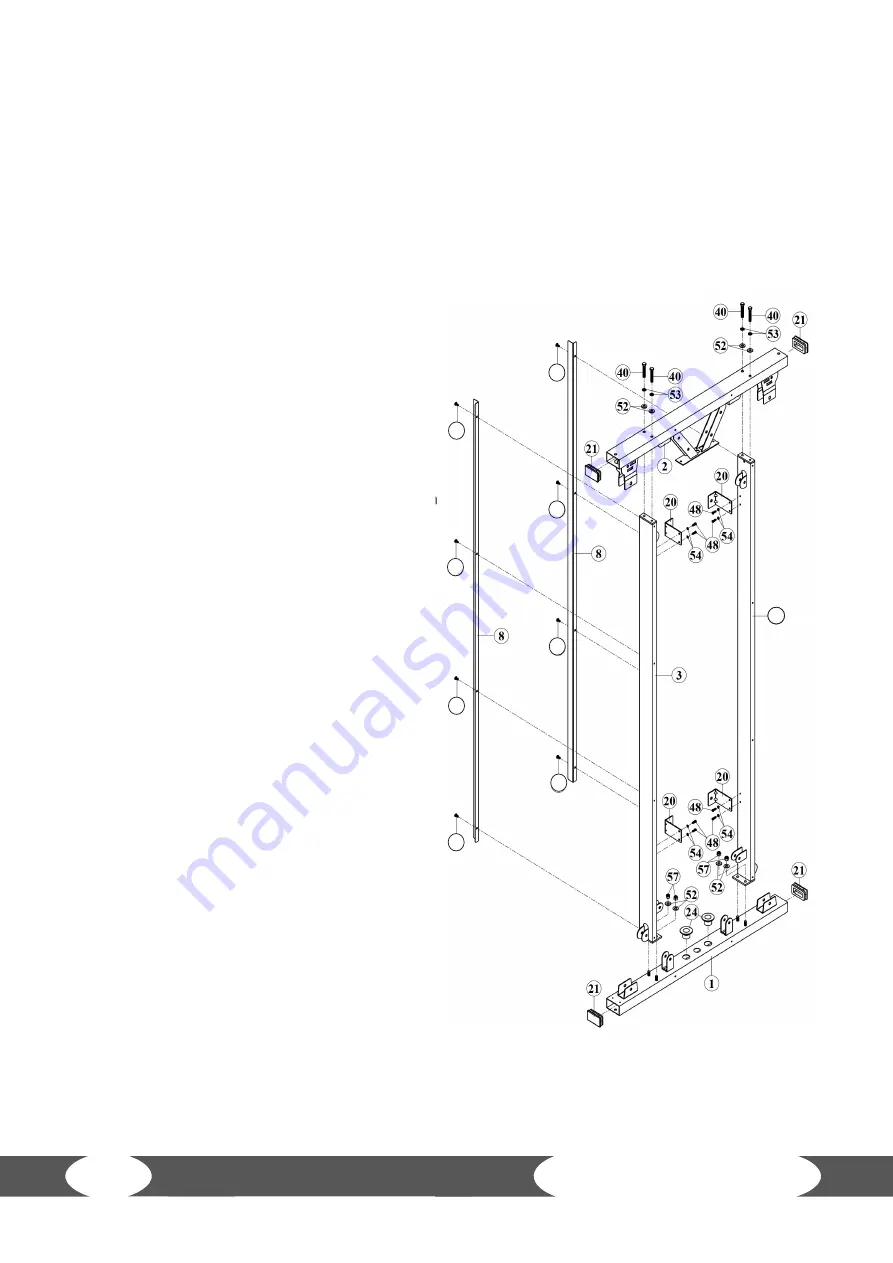
Step 1
1. Place two End Caps (21) and the two Plastic
Guide Rod Holders (24) on the Base
Frame (1).
2. Place two End Caps (21) on the Top
Frame (2).
3. Mount the right and left Main Upright
Frame (3) to the Base Frame (1) using four
washers (52) and four nylon nuts (57).
4. Mount the Right and left Main Upright
Frame (3) to the Top Frame (2) using
four bolts (40), four spring washers (53)
and four washers (52).
5. Mount the Rear Covers (8) to the Main
Upright Frames (3) using eight screws
(47).
6. Mount the L-Shaped Brackets (20) to
the Main Upright Frames (3) using
eight screws (48) and eight spring
washers (54).
7. Tighten all bolts and screws.
3
Summary of Contents for DESIGN LINE DUAL PULLEY
Page 2: ...2 Dual Pulley ...
Page 4: ...4 Dual Pulley ...
Page 11: ... 21 23 24 26 27 28 29 32 33 34 35 37 38 39 40 42 43 51 52 53 56 57 55 36 11 ...
Page 15: ...15 ...
Page 17: ...3 17 ...
Page 19: ...3 3 19 ...
Page 21: ...3 21 ...
Page 29: ...47 47 47 47 47 47 47 47 3 29 7 3 Exploded Drawing ...
Page 34: ...34 Dual Pulley ...
Page 35: ...35 Notes ...


