ULTRA TRAINER
15
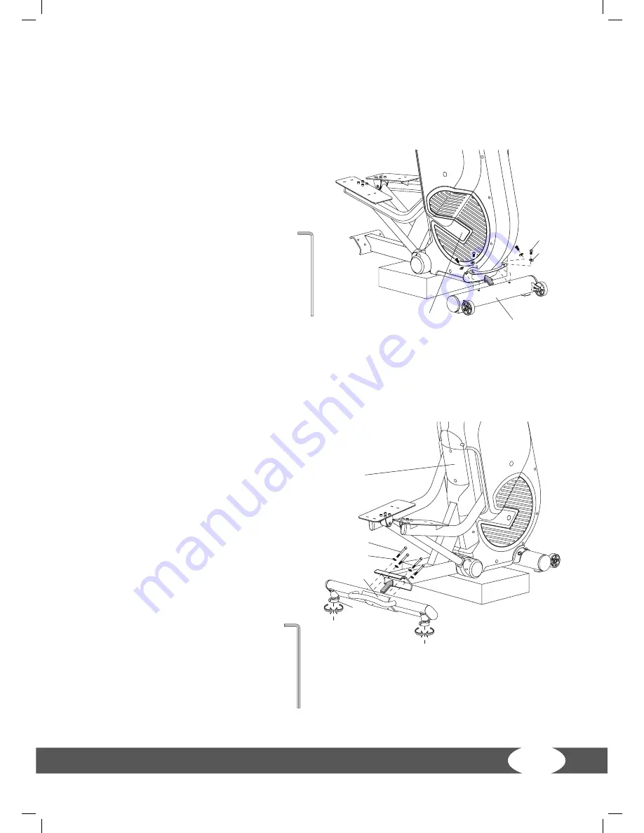
Step 3:
Assembly of the front base
(1)
Mount the front base (B) with the screw (J2) and the washer (J3) on the bracket of
the main frame (A).
Note:
The J2 screws were removed ac-
cording to figure 2.
Step 4:
Assembly of the rear base
(1)
Mount the rear base (C) with the
screw (J4) and the washer (J9) on the
bracket of the main frame (A).
(2)
After the assembly, you can place the
machine completely on the floor.
Note:
Align the levelling feet (C5) at the
bottom of the rear base so that the ma-
chine stands even and stable.
B
A
J2
J3
6 m/m
6 m/m
J4
A
J9
C
C5
B
A
J2
J3
6 m/m
6 m/m
J4
A
J9
C
C5
B
A
J2
J3
6 m/m
6 m/m
J4
A
J9
C
C5
B
A
J2
J3
6 m/m
6 m/m
J4
A
J9
C
C5


