background image

Assembly 

(Cont.) 

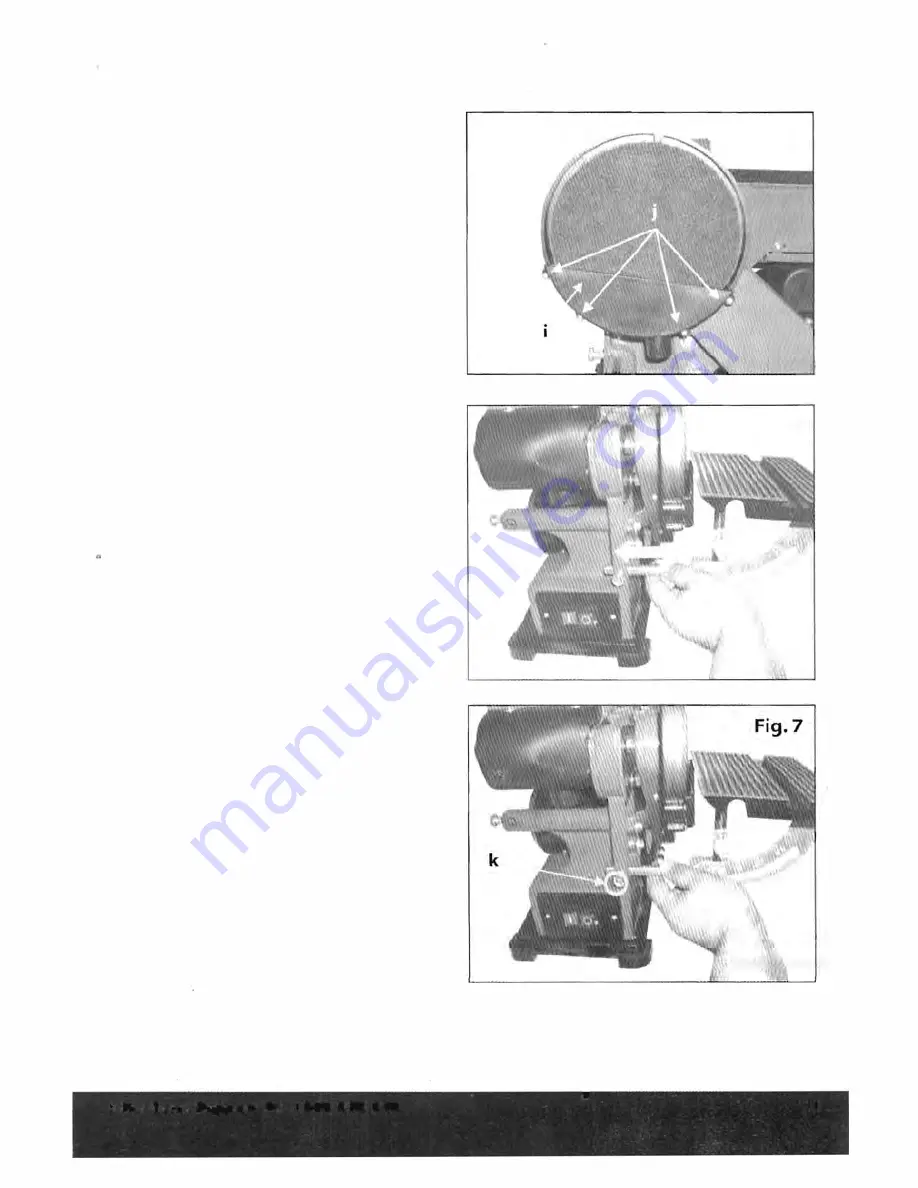
Installing  Disc  Guard  with  Dust 

Outlet (Fig. 

5): 

• 

Position  disc  guard  (i)  against  the 

lower  one-third  of  the  disc,  aligning 

four holes  Ul  as shown in Fig. 

5. 

• 

Using the four screws securely tighten 

the disc guard  into place. 

Mounting  the  Worktable  for  use 
with  the  Disc  Sander  (Fig. 

6  & 

Fig.7): 

• 

Insert  the  worktable  support  bar  into 

the hold as shown in  Fig. 

6. 

• 

Position  the worktable no  further  than 

1.6mm from  the sanding surface. 

• 

Tighten the hex  set  screw  (k)  with the 

spanner  provided (Fig. 

7). 

Fig.S 

Fig.6 

After Sales Support Tel: 1300-355-255 

11 

Summary of Contents for TTA-11241

Page 1: ... E e N2703 375W BELT DISC SANDER MODEL NO TTA 11241 INSTRUCTION MANUAL AFTER SALES SUPPORT 1300355255 ...

Page 2: ......

Page 3: ...unting Belt Sanding Baffle Mounting the Plastic Feet Mounting the Worktable for use with the Belt Sander Disassembly the Worktable Mounting the Worktable Adjustment Adjusting the Belt Tracking To adjust BeltTracking Squaring the Worktable to the Sanding Disc Adjusting the Worktable Operation Switch ON OFF Bevel Sanding ToTilt the Worktable Mitre Sanding Vertical Sanding Surface Sanding on the Sand...

Page 4: ...date of purchase we will remedy the problem as quickly as possible once it has been brought to our attention In the unlikely event of such an occurrence or if you require any information about the product please refer to the troubleshoot chart in this manual or contact us via our after sales support service line details of which can be found in this manual and on the product itself We strongly rec...

Page 5: ...10 Mitre Gauge 3 Upper Sanding Drum Guard 11 Bevel Gauge 4 Belt Sanding Baffle 12 Table Tilting Lock 5 Sanding Belt Knob 6 Tracking Adjust Knob 13 Plastic Feet 7 Belt Tension Lever 14 Dust Outlet 8 Sanding Disc 15 Dust Outlet After Sales Support Tel 1300 355 255 3 ...

Page 6: ...understand instruction manual before using this product Wear hearing protection Wear eye protection Wear breathing protection Wear safety gloves Contents of Carton x Belt Disc Sander 375W x Mitre Gauge x Spanner x Allen Key x Working Table 1 x Sanding Disc 4 x Rubber Feet N2703 Denotes risk of personal injury loss of life or damage to the tool in case of non observance of the instructions in this ...

Page 7: ...e plug in any way Do not use any adapter plugs with earthed grounded power tools Unmodified plugs and matching outlets will reduce the risk of electric shock Avoid body contact with earthed or grounded surfaces such as pipes radiators ranges and refrigerators There is an increased risk of electric shock if your body is earthed or grounded Do not expose power tools to rain or wet conditions Water e...

Page 8: ...r control of the power tool in unexpected situations Dress properly Do not wear loose clothing or jewellery Keep your hair clothing and gloves away from moving parts Loose clothes jewellery or long hair can be caught in moving parts If devices are provided for the connection of dust extraction and collection facilities ensure these are connected and properly used Use of these devices can reduce du...

Page 9: ...s and the work to be performed Use of the power tool for operations different from those intended could result in a hazardous situation Service Have your power tool serviced by a qualified repair person using only identical replacement parts This will ensure that the safety of the power tool is maintained Health Advice WARNING When drilling sanding sawing or grinding dust particles will be produce...

Page 10: ...pulleys Make sure the sanding belt runs in the proper direction See directional arrow on back side of belt Mak sure the sanding belt or disc is not torn or loose Support workpiece firmly with the mitre gauge backstop or work tabfe when sanding with the belt Note The only exception is curved work performed on the top wheel of belt Always hold the workpiece firmly on the table when sanding on the di...

Page 11: ...tlet Replace missing damaged or failed parts before resuming operation The use of attachments and accessories not recommended by Taurus may result in the risk of injuries WARNING Some dust particles created by power sanding sawing grinding drill and other construction jobs contain chemicals known to cause cancer birth defects or other reproductive harm Some examples of these chemicals are Lead fro...

Page 12: ...Slide sanding disc plate c onto drive shaft d making certain key e in drive shaft d fits into keyway f of disc plate Fig 2 Insert hex wrench g1 down through slot h in the back of disc guard a and tighten set screw holding disc plate on Assembling Sanding Disc to Disc Plate Fig 4 Make sure sanding disc plate c is clean Peel backing from sanding disc 8 and press disc firmly into position all around ...

Page 13: ...he four screws securely tighten the disc guard into place Mounting the Worktable for use with the Disc Sander Fig 6 Fig 7 Insert the worktable support bar into the hold as shown in Fig 6 Position the worktable no further than 1 6mm from the sanding surface Tighten the hex set screw k with the spanner provided Fig 7 Fig S Fig 6 After Sales Support Tel 1300 355 255 0 11 ...

Page 14: ...s on the upper sanding drum guard Fig SB Fasten the belt lock washer and flat washer as shown in Fig SA LMounting the Plastic Feet Fig 9A Fig 9B The plastic feet can protect your table and floor Position the edge of the tool feet in the groove of the plastic feet Fig 9A Fig 8A Fig 8B After Sales Support Tel 1300 355 255 12 ...

Page 15: ...the work table for vertical sanding Disassemble the worktable Loosen and remove the head screw and the washer as shown in Fig lOA Loosen and remove the head screws and the washers as shown in Fig lOB and Fig 10C Remove the worktable 4 Fig lOA Fig lOB Fig l0C After Sales Support Tel 1300 355 255 13 ...

Page 16: ... into the hold Fig 11A Position the worktable no further than 1 6mm from the sanding surface Fig 11 B Tighten the hex set screw with the spanner 92 Fig 11 C Make sure the worktable hex screw is fully secured Fig llA Fig 11B Fig 11C After Sales Support Tel 1300 355 255 14 ...

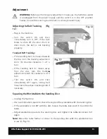
Page 17: ...stment knob 6 counter clockwise 114 of a turn If the sanding belt 5 moves away from the disc turn the tracking adjustment knob 6 clockwise of a turn Turn the switch ON and then immediately OFF again noting belt movement Re adjust tracking knob if necessary Fig 12 Squaring the Worktable to the Sanding Disc Unplug the machine Use a combination square to check the angle of the worktable with the sand...

Page 18: ...ng small items on the disc sander always use the left hand side of the disc The worktable can be tilted from 0 to 45 for bevel sanding To tilt the worktable Loosen the table lock knob 12 by turning it counter clockwise Set the worktable to the desired angle with the bevel gauge 11 Note Position the worktable no further than 1 6mm from the sanding surface Tighten the table lock knob 12 by turning i...

Page 19: ...for the vertical sanding operation Note Sand a long work piece with the sanding belt in the vertical by moving the work evenly across the sanding belt Surface Sanding on the Sanding Belt Fig 18 Hold the work piece firmly keeping fingers away from the sanding belt Keep the end pressed firmly against the belt sanding baffle moving work evenly across the sanding belt Note Use extra caution when sandi...

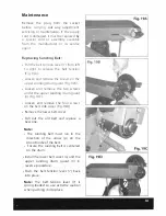
Page 20: ...n and remove the two screws under the upper sanding drum guard n Fig 19C Loosen and remove the four screws on the belt side cover Fig 190 Remove the lower belt cover Pull out the old belt and replace a new one Note The sanding belt must run in the direction of the arrow p on the smooth side of the belt Ensure the sanding belt is centered on the drum Install the lower belt cover 0 and the upper san...

Page 21: ...le to help keep the surfaces clean Never use water or chemical cleaners to clean your power tool Always store your power tool in a dry place Keep the motor ventilation slots clean Keep all working controls free of dust If you see some sparks flashing in the ventilation slots this is normal and will not damage your power tool After Sales Support Tel 1300 355 255 19 ...

Page 22: ...Notes After Sales Support Tel 1300 355 255 20 ...

Page 23: ......

Page 24: ......

Reviews: