X10.5 Pro SMART
18
Step 7:
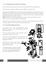
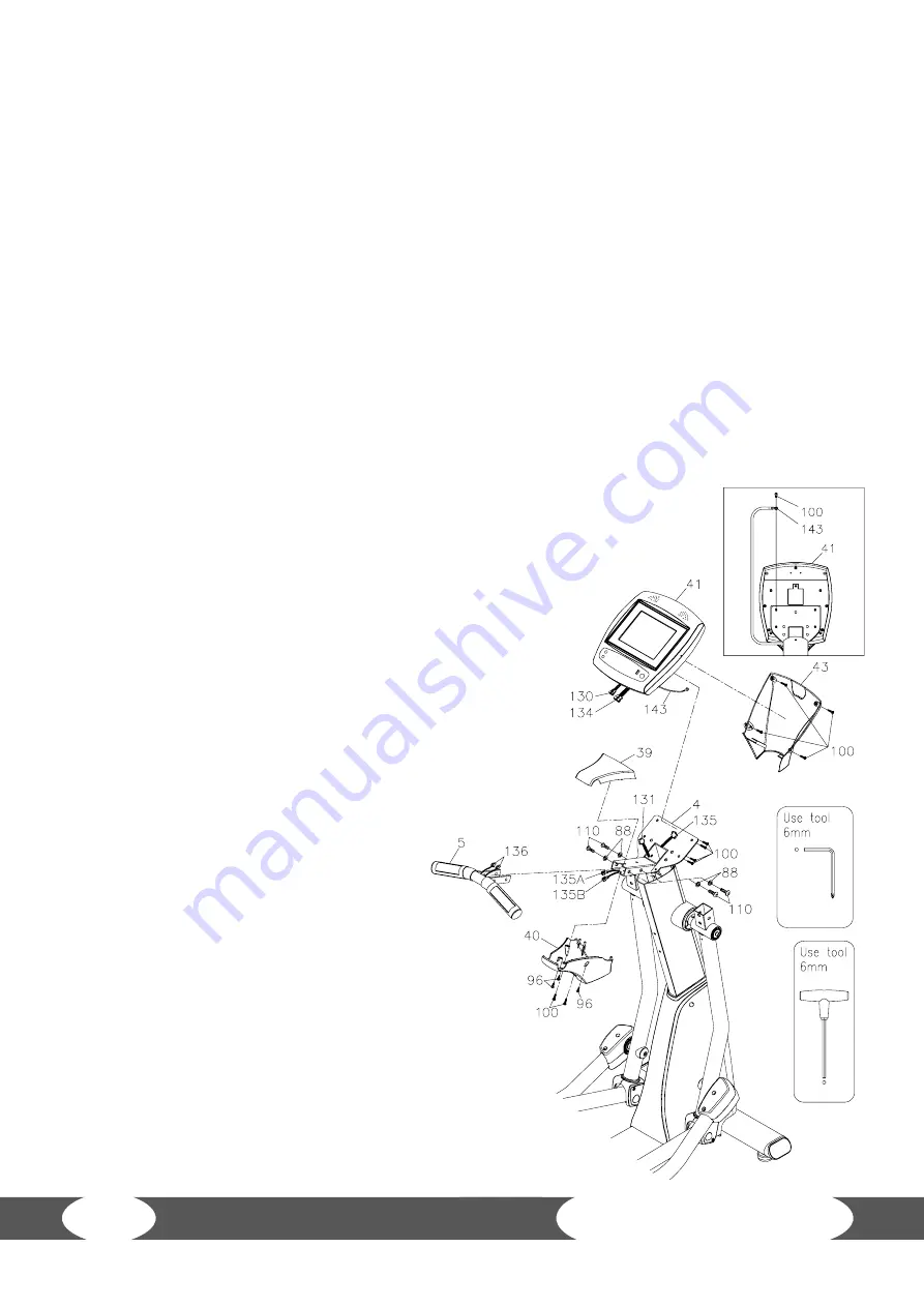
Assemble console and cable connections
a) Connect the upper connecting cable (130) to the middle connecting cable (131).
b) Connect the upper pulse cable (134) to the middle pulse cable (135).
c) Refer to FIG.1 and place the console (41) onto the upright post (4). First screw one screw
(M5xp0.8x15mm)(100) through the screw hole of the ground wire (143) and then attach it
to the back of top left screw hole, which is located on the back of the upright post bracket
(like the drawing shown on the left side).
Note: this process is necessary to prevent any electric interference from the console.
Then secure this screw (M5xp0.8x15mm) (100) fully.
d) Follow the main drawing to secure the rest of three screws (M5xp0.8x15mm)(100) fully
in order to tighten the console (41) onto the upright post (4).
Step 8:
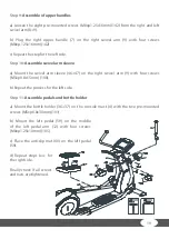
Assemble handle and covers
a)
Loosen
the
four
pre-mounted
screws
(M8x1.25x16mm)(110) and spring washers (88) from
the fixed handle (5).
b) Connect the lower pulse cable (136) with the two
middle pulse cables (135A+135B).
c) Mount the fixed handle (5) on the console mast (4)
with four screws (M8xp1.25x16mm)(110) and four
spring washers (88).
d) Mount the console cover (43) on
the console (41) with four screws
(M5xp0.8x15mm)(100).
e) Mount the upper and lower handle
cover (39+40) on the console mast (4)
with three screws (M4x20mm)(96) and
two screws (M5xp0.8x15mm) (100).
/
0

