15
4.2
O
PERATION
If you removed the cover to adjust to set the cartridge loading and gain switches, you must replace it
before operating the unit. To avoid a risk of electric shock, never operate the unit with the cover
removed.
When the unit is switched on, it goes through a 40 second warmup sequence before the blue “ready”
LED turns on. The phono stage will not pass signal until the blue “ready” LED is on. Before playing an LP,
turn down the volume control on your amplifier until you are familiar with the required gain setting.
4.3
T
UBE
R
EPLACEMENT AND
S
UBSTITUTION
Vacuum tubes last much longer than most people realize, and although the lifetime of any particular
tube is impossible to predict, hopefully it should be many years before any tube replacement is
necessary. Replace tubes with the same type: only 6SL7GT tubes can be used in the phono stage. In
particular, many people confuse the 6SL7 with the 6SN7. Unfortunately, the 6SN7 cannot be used in any
position in the phono stage.
The unit is normally supplied with either Sovtek 6H9C/6SL7GT or Tung Sol Reissue 6SL7GT tubes. It is
also OK to use new, old-stock (NOS) 6SL7GT tubes in the phono stage, although they do tend to be
noisier, so you should be aware of potentially higher noise if you do use them. Noise is primarily an issue
with the input tube (the right front tube). The noise levels in the electronics are well below the surface
noise on vinyl LPs, so you may wish to choose the input tube by other criteria as well.
The tubes are much easier to remove if the cover is removed first. Before removing the cover, unplug
the unit and wait 10 minutes for the internal capacitors to discharge. Remove the cover by removing 4
screws on the sides of the enclosure. If you do remove the cover, you must replace it before operating
the unit. To avoid a risk of electric shock, never operate the unit with the cover removed.
Summary of Contents for 6SL7
Page 1: ...TAVISH DESIGN LLC Made in U S A Vintage 6SL7 Phono Stage MM MC Assembly and Setup Manual...
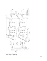
Page 19: ...18 Fig 5 3 Schematic sheet 1 of 4...
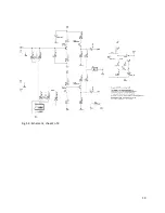
Page 20: ...19 Fig 5 4 Schematic sheet 2 of 4...
Page 21: ...20 Fig 5 5 Schematic sheet 3 of 4...
Page 22: ...21 Fig 5 6 Schematic sheet 4 of 4...


