4
3
A
SSEMBLY
Warning: This amplifier uses high voltages which could cause an electrical shock, possibly resulting in
injury or death. Therefore, these assembly instructions are intended for electronics technicians (or
those with equivalent skills) having experience with high-voltage electronics. The usual safety
procedures required when working with high voltages must be followed, and they are described only
briefly in these instructions. If you are unfamiliar with these procedures, you should not attempt
assembly. Please read through these instructions before beginning assembly. If you are in doubt
about your ability to safely and successfully assemble the kit, please send it back, or first get some
experience with other electronics kits. No liability is assumed by Tavish Design, LLC. The ARRL
Handbook for Radio Amateurs
1
has a useful chapter on electrical safety.
Kit assembly requires a soldering iron with a fine tip and a digital multimeter (DMM), along with other
normal electronics workshop tools.
Unpack the box and verify the following items:
Quantity Item
1
Printed circuit board (4 JFETs are pre-installed on the PCB in the complete kit)
1
Enclosure
1
Decorative flange
1
Wall transformer
1
Bag of 58 metal film resistors
1
Bag of 27 carbon film or metal oxide resistors, and trimmers
1
Bag of 20 electrolytic capacitors
1
Bag of 19 film capacitors
1
Bag of 25 diodes, transistors, and ICs (not including 4 JFETs, which are pre-installed)
1
Bag of 19 miscellaneous PCB-mounted components
3
Tube sockets
1
Bag of hardware and chassis-mounted components, including switch and panel LEDs
3
Vacuum tubes (Sovtek 6H9C/6SL7GT)
1
PC mounted toroidal transformer
Detailed parts lists are included in tables 5.2 – 5.6. Use the schematic, parts lists, and parts placement
diagram in section 5 to identify the correct location for parts.
1
http://www.arrl.org/shop/ARRL-Handbook-2015-Softcover-Edition/
Summary of Contents for 6SL7
Page 1: ...TAVISH DESIGN LLC Made in U S A Vintage 6SL7 Phono Stage MM MC Assembly and Setup Manual...
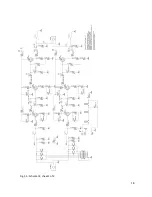
Page 19: ...18 Fig 5 3 Schematic sheet 1 of 4...
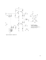
Page 20: ...19 Fig 5 4 Schematic sheet 2 of 4...
Page 21: ...20 Fig 5 5 Schematic sheet 3 of 4...
Page 22: ...21 Fig 5 6 Schematic sheet 4 of 4...


