10
Compact design
Tavrida Electric develops and produces all vital parts of the circuit breakers themselves. The result of intensive
inhouse fundamental and material research are extremely compact vacuum interrupter and magnetic actuators.
Optimal selection of all components makes these the most compact and light weight vacuum circuit breaker in
the world.
Long life
Contact erosion is minimised by use of axial magnetic field. All the switching elements are assembled axially and
symmetrically in one straight line. This means that all the mechanical movements are exclusively direct and linear.
30 000 operating cycles can be achieved with rated current without replacing or adjusting any components.
Maintenance free
The ISM is maintenance-free over the expected life of at least 25 years.
Highest availability
In addition to minimising the number of failure-critical components, the Tavrida Electric circuit breaker monitors
its status continuously. In the unlikely event that a fault occurs it is indicated and can be rectified before an unsuc-
cessful switching attempt is made. This leads to higher availability of the electric power supply system.
Des ign and Method of Operation: ISM and CM
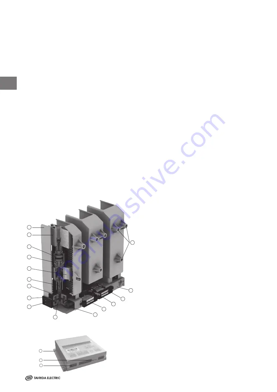
The ISM vacuum circuit breaker uses three single-coil magnetic actuators, one per pole. The three actuators are
mounted in a steel frame and mechanically linked by a synchronizing shaft (Figure 3).
1. Support insulator
2. Upper terminal
3. Vacuum interrupter
4. Movable contact with bellows
5. Lower terminal
6. Pulling insulator
7. Actuator stator
8. Opening and contact pressure springs
9. Actuator coil
10. Actuator armature
11. Synchronizing shaft
12. Auxiliary contacts
13. Interlocking shaft
14. Main contacts position indicator link
15. Frame
16. Fixing points
Figure 3
View into the ISM
Indoor Switching Module (ISM)
1
2
3
4
6
7
10
13
5
14
15
12
11
16
8
9
1
1. Terminals
2. LED indicators
3. Fastening holes
4. Grounding stud
Control Module (CM)
3
2
1
Figure 4
Control Module
Summary of Contents for ISM Shell_2 Series
Page 2: ...2...
Page 6: ...6 1 THIS PAGE INTENTIONALLY LEFT BLANK...
Page 7: ...7 Introduction 1...
Page 12: ...12 1 THIS PAGE INTENTIONALLY LEFT BLANK...
Page 13: ...13 Receiving Handling and Storage 2...
Page 19: ...19 Ins tallation 3...
Page 36: ...36 3 THIS PAGE INTENTIONALLY LEFT BLANK...
Page 37: ...37 Switching and Control Functions 4...
Page 41: ...41 Commiss ioning Maintenance 5...
Page 44: ...44 5 THIS PAGE INTENTIONALLY LEFT BLANK...
Page 45: ...45 Signalling 6...
Page 49: ...49 Special Applications Fast Switching 6...
Page 53: ...53 Product Line 7...
Page 55: ...55 Dimens ions and Weights 8...
Page 61: ...61 8 Mating part with interlocking lever Interlockingshaftwithmountedinterlockinglever...
Page 62: ...62 Circuit Diagrams 9...
Page 63: ...63 ISM15_Shell_2 with CM_1501_01 9...
Page 64: ...64 ISM15_Shell_2 with CM_16_1 9...
Page 65: ...65 9 THIS PAGE INTENTIONALLY LEFT BLANK...
Page 66: ...66 Technical Data 10...
Page 71: ...71 10 THIS PAGE INTENTIONALLY LEFT BLANK...
Page 72: ...72 Regulations and Ambient Conditions 11...
Page 74: ...74 Legal Information 12...
Page 77: ...77 12 THIS PAGE INTENTIONALLY LEFT BLANK...
Page 79: ...79 Date 12...
Page 80: ...80 Date 12...
Page 81: ...81 Date 12...


