27
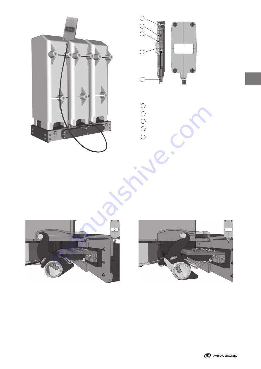
1
2
3
4
5
Frame
Spring
Indicator plate
Window
Adjusting mechanism
1
2
3
4
5
Indication of ISM-position by indicator plate depending on position of synchronizing shaft trunnion
Figure 37
Position indicator with flexible link
Figure 38
Position of trunnion at opened ISM
Figure 39
Position of trunnion at closed ISM
3
Summary of Contents for ISM Shell_2 Series
Page 2: ...2...
Page 6: ...6 1 THIS PAGE INTENTIONALLY LEFT BLANK...
Page 7: ...7 Introduction 1...
Page 12: ...12 1 THIS PAGE INTENTIONALLY LEFT BLANK...
Page 13: ...13 Receiving Handling and Storage 2...
Page 19: ...19 Ins tallation 3...
Page 36: ...36 3 THIS PAGE INTENTIONALLY LEFT BLANK...
Page 37: ...37 Switching and Control Functions 4...
Page 41: ...41 Commiss ioning Maintenance 5...
Page 44: ...44 5 THIS PAGE INTENTIONALLY LEFT BLANK...
Page 45: ...45 Signalling 6...
Page 49: ...49 Special Applications Fast Switching 6...
Page 53: ...53 Product Line 7...
Page 55: ...55 Dimens ions and Weights 8...
Page 61: ...61 8 Mating part with interlocking lever Interlockingshaftwithmountedinterlockinglever...
Page 62: ...62 Circuit Diagrams 9...
Page 63: ...63 ISM15_Shell_2 with CM_1501_01 9...
Page 64: ...64 ISM15_Shell_2 with CM_16_1 9...
Page 65: ...65 9 THIS PAGE INTENTIONALLY LEFT BLANK...
Page 66: ...66 Technical Data 10...
Page 71: ...71 10 THIS PAGE INTENTIONALLY LEFT BLANK...
Page 72: ...72 Regulations and Ambient Conditions 11...
Page 74: ...74 Legal Information 12...
Page 77: ...77 12 THIS PAGE INTENTIONALLY LEFT BLANK...
Page 79: ...79 Date 12...
Page 80: ...80 Date 12...
Page 81: ...81 Date 12...


