102
Internal fault of the driver module.
None
Replace the RCM
IOM Fault
Possible reason
Malfunction identification procedure
Corrective action
Internal fault of the Input/Output module. None
Replace the IOM. If the new IOM does
not work as well, replace the RCM
together with the IOM
RTU Short Circuit
Possible reason
Malfunction identification procedure
Corrective action
Internal RTU short circuit
Disconnect the RTU from the power supply
Turn the RTU supply on via the MMI If signal
disappears short circuit is inside the RTU
Replace RTU
Short circuit in the wires connecting RTU
and RCM
If the signal does not
disappear disconnect Plug “10”
If the signal disappears the short circuit is in the
wiring between the RTU and the RCM
Replace the wiring
RCM malfunction
If the signal does not disappear the problem is in the
RCM
Replace the RCM
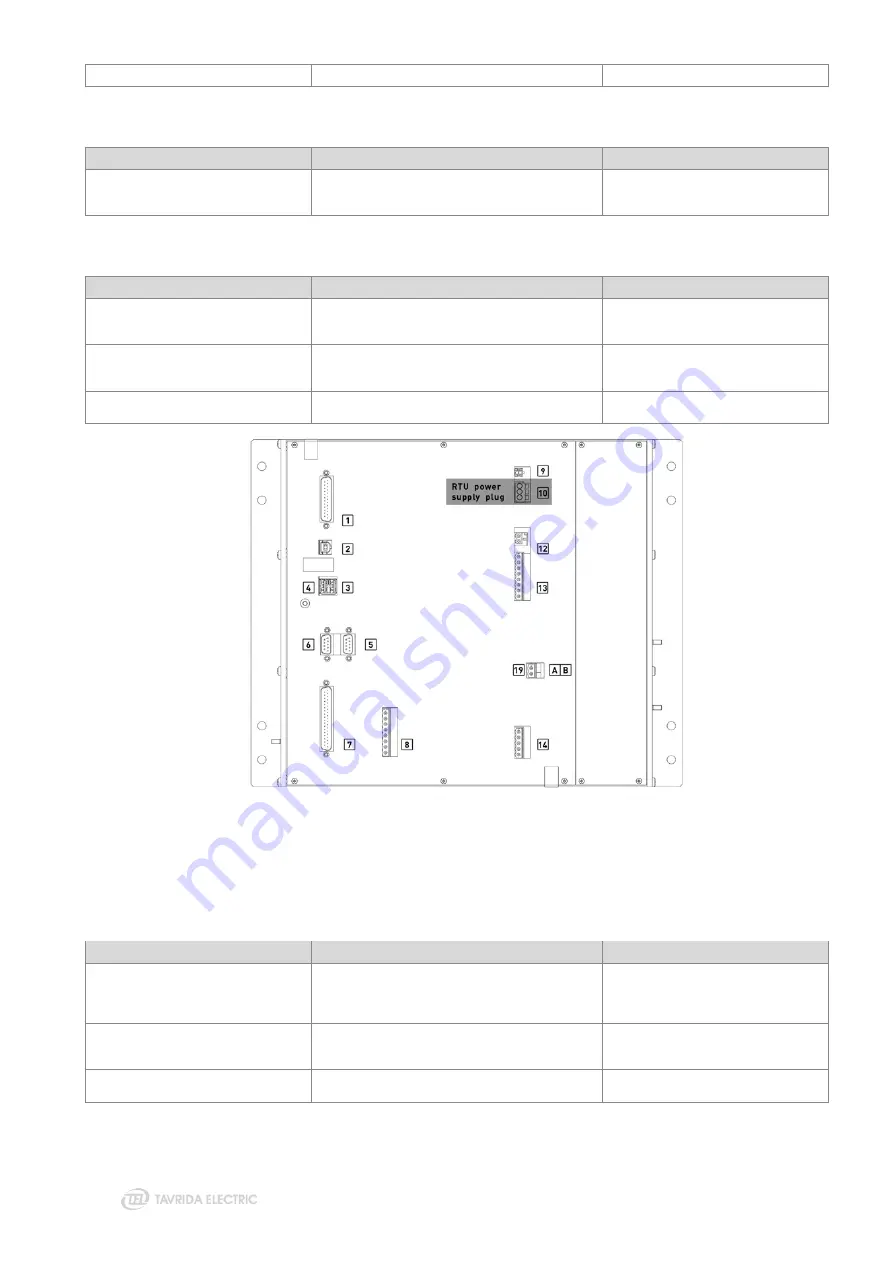
Figure 77
RTU power supply plug at RCM
NOTE!
Wire numbers shall comply with the numbers of the socket.
Loss of AC Supply
Possible reason
Malfunction identification procedure
Corrective action
Auxiliary voltage transformer malfunction
Check the voltage at the power supply input
terminals (Figure 78) If the voltage is less than 85 V
it is a malfunction of the auxiliary voltage
transformer
Check the auxiliary voltage transformer
and its wiring, fix the malfunctioning
component
PSFM malfunction
If the voltage is between 85-265 V, check the
voltage at the RCM input (Figure 79) If the voltage
is less than 85 V, the malfunction is in the PSFM
Replace PSFM
RCM malfunction
In case the voltage at the RCM inputs is between
85-265 V it is an RCM malfunction
Replace the RCM
Summary of Contents for Rec15
Page 1: ......
Page 5: ...1 Introduction...
Page 9: ...2 Technical Parameters...
Page 14: ...3 Product Description...
Page 26: ...26 Figure 25 Anti vandal housing...
Page 27: ...4 Functionality...
Page 56: ...5 Product Handling...
Page 69: ...6 Installation...
Page 81: ...7 Commissioning...
Page 84: ...8 Operation...
Page 99: ...99 Figure 76 Settings uploading wizard...
Page 100: ...9 Maintenance and Troubleshooting...
Page 114: ...114 Figure 90 Securing the trip hook shaft against rotation...
Page 115: ...10 Product Coding...
Page 122: ...11 Appendices...
Page 128: ...128 Appendix 4 Recloser Control Drawings Figure 99 Dimensions of RC5_4...
Page 133: ...133 Figure 106 Dimensions of standard OSM mounting kit arrangement for lateral installation...
Page 134: ...134 Figure 107 Dimensions of interface bracket...
Page 135: ...135 Figure 108 Dimensions of OSM mounting kit with M16 pole interface front installation...
Page 136: ...136 Figure 109 Dimensions of OSM mounting kit with M16 pole interface lateral installation...
Page 137: ...137 Figure 110 Dimensions of OSM mounting kit with M20 pole interface front installation...
Page 138: ...138 Figure 111 Dimensions of OSM mounting kit with M20 pole interface lateral installation...
Page 149: ...149 Figure 122 Dimensions of OSM substation mounting kit...
Page 152: ...152 Figure 125 Dimensions of RC mounting kit for through the pole installation...
Page 153: ...153 Figure 126 Dimensions of RC substation mounting kit...
Page 154: ...154 Figure 127 Dimensions of VT mounting kit One VT holder...
Page 163: ...163 Appendix 8 Connectors Drawings Figure 141 Dimensions of aerial connector...
Page 164: ...164 Figure 142 Dimensions of bird guards for aerial connector...
Page 165: ...165 Figure 143 Dimensions of two hole NEMA connector...
Page 166: ...166 Figure 144 Dimensions of bird guards for two hole NEMA connector...
Page 167: ...167 Figure 145 Dimensions of four hole NEMA connector...
Page 168: ...168 Figure 146 Dimensions of bird guards for four hole NEMA connector...
Page 169: ...169 Figure 147 Dimensions of Burndy NEMA connector...
Page 170: ...170 Appendix 9 Recloser Control Wiring Diagram Figure 148 RC5_4 wiring diagram...
Page 172: ......


