53
Digital Input/Output Interface (IOI)
The IOI provides control and indication via the digital Input-Output Module (IOM). The IOM provides 12 digital
inputs and 12 digital outputs for SCADA control and indication. Each input/output function is individually
customizable.
4.4 Remote Engineering
The TELARM Dispatcher Interface (TDI) enables multiple recloser connections to Tavrida Electric TELARM
Dispatcher® for remote control and supervision. TELARM Dispatcher can be installed on one or multiple PCs
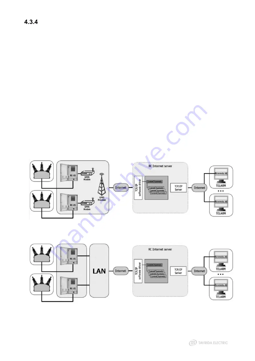
with full or limited access to all or some of the reclosers. Connection via Internet or Local Area Network (LAN)
is available. Physical connection of an RC5_4 to the Internet can be done via wireless connection - GPRS
modem (Figure 28) or wired connection - USB-Ethernet module (Figure 29).
Both the RC5_4 recloser control(s) and PC(s) with TELARM software can connect to RC Internet Server
software (RCIS). This software provides communication between a PC and multiple RC5_4. RCIS itself is a
Windows® service. Connection between TELARM software and RCIS is protected with SSL encryption.
Individual certificates are issued for each PC with TELARM which will connect to RCIS.
Benefits of using a TDI are the following:
•
Remote control is available even without a SCADA system in place (or as backup for existing SCADA
system).
•
SCADA is usually available in dispacther centers only. With TDI regional operators can check protection
devices remotely without any support request form the Dispatcher Center.
•
Potential problems can be identified and eliminated faster because all logs from protection device, including
Event log, detailed Fault profile and fault oscillography are available remotely and can be analyzed by an
operator immediately after protection device has operated.
Figure 28
Structure of the system with wireless connection
Figure 29
Structure of the system with wired connection
Summary of Contents for Rec15
Page 1: ......
Page 5: ...1 Introduction...
Page 9: ...2 Technical Parameters...
Page 14: ...3 Product Description...
Page 26: ...26 Figure 25 Anti vandal housing...
Page 27: ...4 Functionality...
Page 56: ...5 Product Handling...
Page 69: ...6 Installation...
Page 81: ...7 Commissioning...
Page 84: ...8 Operation...
Page 99: ...99 Figure 76 Settings uploading wizard...
Page 100: ...9 Maintenance and Troubleshooting...
Page 114: ...114 Figure 90 Securing the trip hook shaft against rotation...
Page 115: ...10 Product Coding...
Page 122: ...11 Appendices...
Page 128: ...128 Appendix 4 Recloser Control Drawings Figure 99 Dimensions of RC5_4...
Page 133: ...133 Figure 106 Dimensions of standard OSM mounting kit arrangement for lateral installation...
Page 134: ...134 Figure 107 Dimensions of interface bracket...
Page 135: ...135 Figure 108 Dimensions of OSM mounting kit with M16 pole interface front installation...
Page 136: ...136 Figure 109 Dimensions of OSM mounting kit with M16 pole interface lateral installation...
Page 137: ...137 Figure 110 Dimensions of OSM mounting kit with M20 pole interface front installation...
Page 138: ...138 Figure 111 Dimensions of OSM mounting kit with M20 pole interface lateral installation...
Page 149: ...149 Figure 122 Dimensions of OSM substation mounting kit...
Page 152: ...152 Figure 125 Dimensions of RC mounting kit for through the pole installation...
Page 153: ...153 Figure 126 Dimensions of RC substation mounting kit...
Page 154: ...154 Figure 127 Dimensions of VT mounting kit One VT holder...
Page 163: ...163 Appendix 8 Connectors Drawings Figure 141 Dimensions of aerial connector...
Page 164: ...164 Figure 142 Dimensions of bird guards for aerial connector...
Page 165: ...165 Figure 143 Dimensions of two hole NEMA connector...
Page 166: ...166 Figure 144 Dimensions of bird guards for two hole NEMA connector...
Page 167: ...167 Figure 145 Dimensions of four hole NEMA connector...
Page 168: ...168 Figure 146 Dimensions of bird guards for four hole NEMA connector...
Page 169: ...169 Figure 147 Dimensions of Burndy NEMA connector...
Page 170: ...170 Appendix 9 Recloser Control Wiring Diagram Figure 148 RC5_4 wiring diagram...
Page 172: ......


