15
3.1 Outdoor Switching Module
The OSM15/25_Al_1 is a three-phase vacuum circuit breaker designed for outdoor application with the rated
maximum voltage of 15.5 kV and 27 kV correspondingly.
The circuit breaker is installed inside of a lightweight aluminum enclosure with a superior corrosion protection
and very heavy pollution areas application rating. The enclosure of the Outdoor Switching Module
encapsulates a magnetic actuator, mechanical trip and lockout mechanism and auxiliary electric circuits that
contain passive electronic components only.
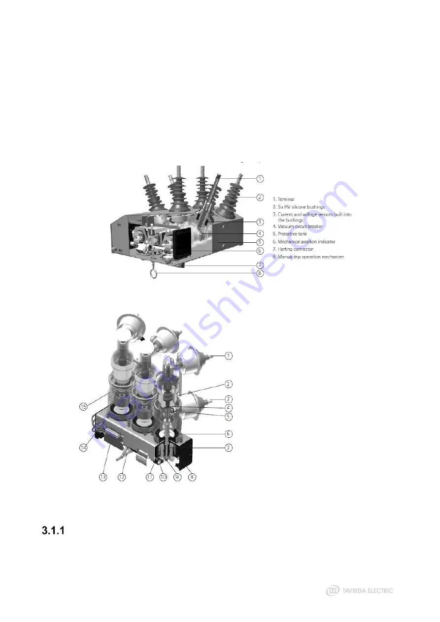
The switching module is equipped with six high voltage bushings with embedded current and voltage sensors.
The bushings are covered by silicone rubber insulation and mount on the top of the tank and provide 500 mm
(OSM15) or 860 mm (OSM25) creepage distance.
The bushings are marked with the terminal designation X1, X2 or X3 for the default source side and X4, X5 or
X6 for the default load side. The source and load side can be reversed in the RC settings if required.
Figure 2
General arrangement of the OSM15/25_Al_1
Figure 3
Internal arrangement of the OSM15/25_Al_1 vacuum circuit breaker
1
Upper terminal
2
Vacuum interrupter
3
Lower terminal
4
Movable contact with bellows
5
Flexible junction shunt
6
Drive insulator
7
Opening and contact pressure spring
8
Magnetic actuator (complete module)
9
Armature
10 Synchronizing shaft
11 Actuator coil
12 Interlocking pins
13 Auxiliary contacts
14 Frame
15 Support insulator
Mechanism Enclosure
The switching module mechanism enclosure is made of a corrosion resistant anodized aluminum alloy. The
enclosure is coated with light gray powder coating.
Summary of Contents for Rec15
Page 1: ......
Page 5: ...1 Introduction...
Page 9: ...2 Technical Parameters...
Page 14: ...3 Product Description...
Page 26: ...26 Figure 25 Anti vandal housing...
Page 27: ...4 Functionality...
Page 56: ...5 Product Handling...
Page 69: ...6 Installation...
Page 81: ...7 Commissioning...
Page 84: ...8 Operation...
Page 99: ...99 Figure 76 Settings uploading wizard...
Page 100: ...9 Maintenance and Troubleshooting...
Page 114: ...114 Figure 90 Securing the trip hook shaft against rotation...
Page 115: ...10 Product Coding...
Page 122: ...11 Appendices...
Page 128: ...128 Appendix 4 Recloser Control Drawings Figure 99 Dimensions of RC5_4...
Page 133: ...133 Figure 106 Dimensions of standard OSM mounting kit arrangement for lateral installation...
Page 134: ...134 Figure 107 Dimensions of interface bracket...
Page 135: ...135 Figure 108 Dimensions of OSM mounting kit with M16 pole interface front installation...
Page 136: ...136 Figure 109 Dimensions of OSM mounting kit with M16 pole interface lateral installation...
Page 137: ...137 Figure 110 Dimensions of OSM mounting kit with M20 pole interface front installation...
Page 138: ...138 Figure 111 Dimensions of OSM mounting kit with M20 pole interface lateral installation...
Page 149: ...149 Figure 122 Dimensions of OSM substation mounting kit...
Page 152: ...152 Figure 125 Dimensions of RC mounting kit for through the pole installation...
Page 153: ...153 Figure 126 Dimensions of RC substation mounting kit...
Page 154: ...154 Figure 127 Dimensions of VT mounting kit One VT holder...
Page 163: ...163 Appendix 8 Connectors Drawings Figure 141 Dimensions of aerial connector...
Page 164: ...164 Figure 142 Dimensions of bird guards for aerial connector...
Page 165: ...165 Figure 143 Dimensions of two hole NEMA connector...
Page 166: ...166 Figure 144 Dimensions of bird guards for two hole NEMA connector...
Page 167: ...167 Figure 145 Dimensions of four hole NEMA connector...
Page 168: ...168 Figure 146 Dimensions of bird guards for four hole NEMA connector...
Page 169: ...169 Figure 147 Dimensions of Burndy NEMA connector...
Page 170: ...170 Appendix 9 Recloser Control Wiring Diagram Figure 148 RC5_4 wiring diagram...
Page 172: ......


