106
De
si
gn
ed
b
y
Ch
ec
ke
d
by
A
ppr
ov
ed
b
y
Dat
e
1 /
1
Edi
ti
on
She
et
Da
te
Sc
al
e
W
ei
ght
Fi
lena
me
Pro
je
ct
io
n
Sw
itc
hi
ng
modul
e
A
. I
shc
henko
A
. M
igunov
V
. M
inaev
18.
02.
2020
18.
02.
2020
A
-
TES
El
ec
tr
ic
al
Int
er
connec
tio
n
Di
ag
ra
m
YA3
YA2
YA1
S4
S15
SC2
M
ag
ne
ti
c
ac
tuat
or
(P
os
iti
on
IS
M
15
_MD
_1
)
A
uxi
liar
y
sw
it
ch
es
M
ain
cont
ac
ts
V
CB
15_
M
D1
_
16D
St
and
ar
d
ci
rc
ui
t
br
eak
er
a
ppl
icat
io
n
(CB
)
S5
S6
S1
S2
S3
(P
os
iti
on
d
ra
w-
ou
t
pl
at
e)
A
uxi
liar
y
sw
it
ch
es
test
posi
tio
n
SQ
2
ser
vi
ce
po
si
tio
n
SQ
1
*
B
-SQ1
Y
A1
, Y
A
2,
Y
A
3
A
ct
ua
to
r
coi
ls;
X
1,
X
3
Ter
mi
na
l bl
oc
k
of
C
on
tr
ol
m
od
ul
e;
X
P1
Pl
ug
c
on
nec
to
r
fo
r
DO
U;
X
1.1
, X
1.2
, X
2.1
, X
2.2
,
X
P2
.1,
X
P2.
2,
X
P2
.3
, X
P2.
4,
In
te
rm
ed
ia
te
w
ir
ing
c
onnec
tor
s
X
P3
.1,
X
P3
.2
, X
S1
.1,
X
S1
.2
SQ
1, S
Q2
A
ux
ilia
ry
s
wi
tc
he
s
of
D
OU
p
os
it
io
n
F1
M
ini
at
ur
e
pr
ot
ec
ti
ve
c
irc
ui
t
br
ea
ke
r
(M
PC
B)
;
F1
sh
oul
d
be
se
lec
te
d
to
w
ith
st
an
d
Co
nt
ro
l m
od
ul
e
in
ru
sh
c
ur
re
nt
le
ve
ls
g
iv
en
in
V
CB
P
ro
du
ct
G
uid
e;
St
at
es
of
t
he
r
el
ays
„M
al
fu
nc
tio
n
or
L
os
s
of
auxi
liar
y suppl
y"
a
nd
„
Re
ad
y"
a
re
s
ho
wn
a
t
po
we
r
su
pp
ly
o
ff
.
St
at
e
of
t
he r
el
ay „
IS
M
mai
n c
ont
ac
t po
sit
ion
" i
s
sho
wn
a
t I
SM
op
en
s
ta
te
. I
t
kee
ps
it
s
pos
iti
on at
absent
of
p
ow
er
suppl
y.
St
at
e
of
t
he
a
ux
ilia
ry
s
wi
tc
he
s
S1
-S
12
is
sh
ow
n
at
IS
M o
pe
n
st
at
e.
Leg
en
d:
*A
W
ir
in
g
of
a
ux
ili
ar
y
sw
itc
hes
, r
el
ay
out
put
s,
ac
cor
di
ng
to
c
ust
om
er
s
pe
cif
ica
tio
n;
*B
SQ
1,S
Q2
a
re
s
ho
w
in
fr
ee
posi
tion
SQ
1 i
s
pr
es
se
d
at
s
er
vi
ce
posi
tion
SQ
2
is
p
re
ss
ed
a
t
test
posi
tion
;
IS
M
In
do
or
s
w
it
chi
ng
mod
ul
e;
IG
BT
Tr
an
si
st
or
br
id
ge
(c
oi
ls
con
tr
ol
);
S1
~
S1
2
A
ux
ilia
ry
s
wi
tc
h
of
IS
M;
S1
3,
S
14
A
ux
ili
ar
y
sw
it
ch
fo
r
IS
M
e
le
ctri
ca
l i
nte
rl
ock
S
13
, S
14
a
re
a
t
in
ac
tiv
at
ed
p
os
iti
on
;
S1
5
A
uxi
liar
y
sw
itc
h
for
IS
M
int
er
lo
ck
S1
5
is
at
inac
ti
vat
ed
pos
it
io
n,
is
n
ot
u
se
d
in
D
OU
.
PB
C
Pu
sh
b
ut
ton
c
lose;
PB
T
Pu
sh
b
ut
ton
o
pen;
CCO
Co
nt
ro
l c
om
m
and
ON
, O
FF;
PC
C1
Pr
ot
ec
ti
on
c
on
tr
ol
c
ont
ac
t;
R1
Resi
st
or
2
2k
Oh
m;
YA
4
Int
er
lo
ck
ing
so
len
oi
d;
V
D1
Di
od
e
br
idg
e
39
41
12
36
37
38
31
29
28
40
54
55
DRA
W-O
UT
UNIT
Indo
or S
wit
chi
ng M
odu
le
Draw
-out
pl
ate
-XT
1
-XT
1
-SQ2
1
3
5
79
24
6
8
-SQ2
48
44
32
33
34
24
23
22
21
46
11
10
12
Cont
rol
M
odule
CM_
16_
1
15
14
13
12
2
1
1
ON
OF
F
4 3
5
7
6
8
2
Rel
ay out
put
Rea
dy
Rea
dy
IS
M p
osi
tion
au
x.sw
itc
h
Mag
ne
tic
ac
tu
at
or
OFF
(dr
y c
ont
ac
ts)
Sw
itc
hin
g c
om
mands
ON
M
an
ual
ge
ner
at
or
(o
pt
ional
)
Pro
tec
tion and
con
tro
l devi
ce
PBC
CCO
CCO
PBT
PCC1
1A
(11
0, 22
0V)
2A(
60V)
4A(
24V)
U= U
~
-F1
*A
Auxi
lia
ry
p
ow
er
su
pp
ly
SA
10
11
Mal
fu
nc
tion
or
Lo
ss o
f au
xil
iar
y
su
ppl
y
R1
1
1
2
2
3
3
4
4
5
5
6
6
7
7
8
8
AA
BB
CC
DD
EE
FF
25
27
26
53
-YA
4
-YA
4
52
YA
4
Int
er
lo
ck
ing
sol
enoi
d
Dr
aw
-o
ut
p
lat
e
(
opt
ion
al
)
9
Mal
func
tion
or
Lo
ss o
f au
xiliar
y sup
ply
-XT
2
1
3
5
7
9
11
2
4
6
8
10
12
-XT
3
S10
S11
S12
S7
S8
S9
8
9
4
5
6
7
20
19
18
15
17
16
1
3
5
7
9
11
2
4
6
8
10
12
1
3
5
79
2
46
8
3
50
47
43
10
45
51
14
11
42
10
12
11
-X
T2
-X
T3
-SQ1
3
2
1
4
-VD
1
-VD
1
Di
od
e B
ridge
Dr
aw
-o
ut
p
la
te
(o
pt
ional
)
2
1
ISM
mai
n con
tac
t po
sition
XS
1.1
XS
1.2
VD
1
XP
3.
1
XP
3.
2
X1
.1
X1
.2
X2
.2
S13
S14
X2
.1
XP
2.
1
XP
2.
3
XP
2.
2
XP
2.
4
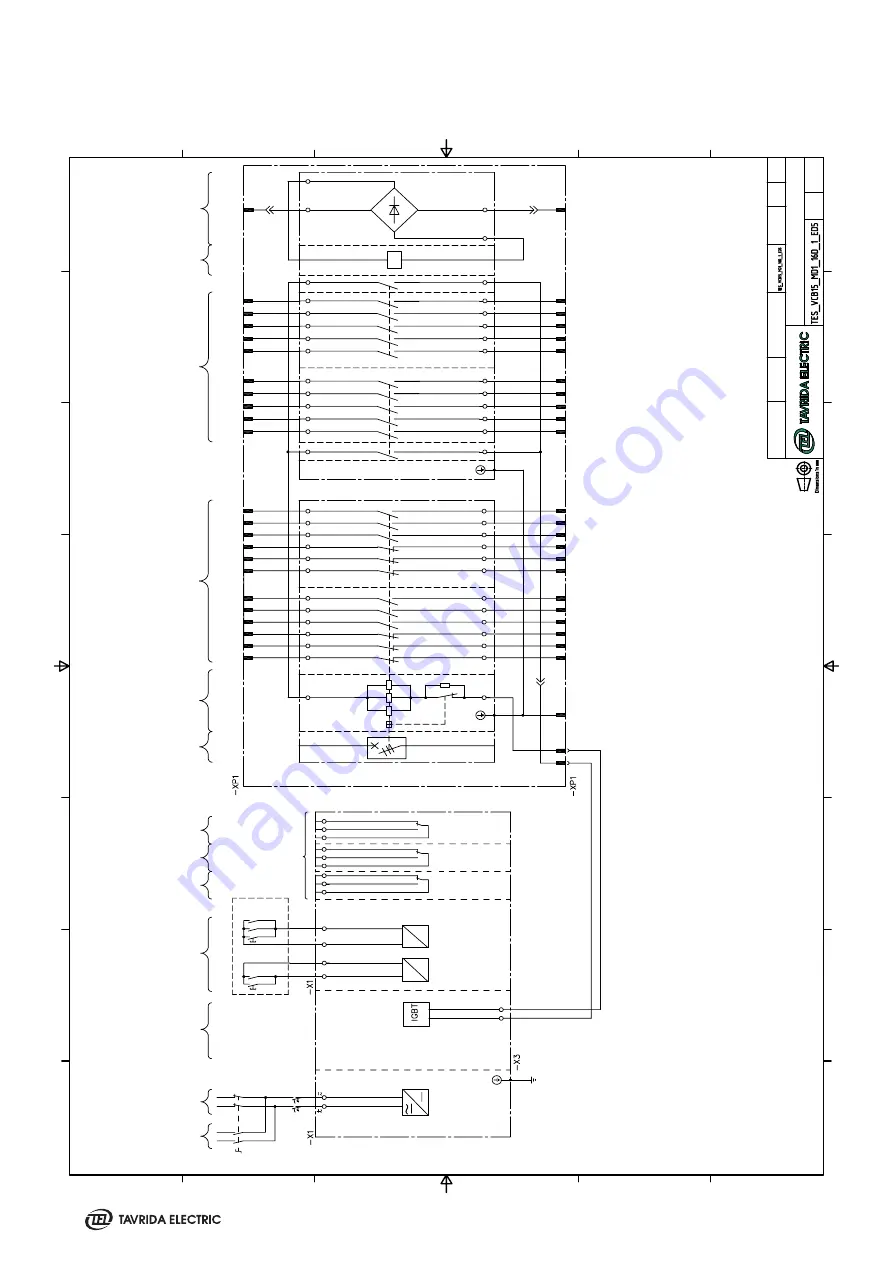
VCB15_MD1_16D with Plastic Plug
Summary of Contents for VCB15
Page 2: ......
Page 4: ......
Page 5: ...1 Introduction...
Page 9: ...2 Presentation...
Page 11: ...3 Product Coding...
Page 23: ...4 Technical Parameters...
Page 33: ...5 Design and Operation...
Page 42: ......
Page 43: ...6 Functionality...
Page 48: ......
Page 49: ...7 Application Notes...
Page 56: ......
Page 57: ...Appendix 1 Type Tests...
Page 61: ...Appendix 2 Withdrawable VCB Package Dimensions...
Page 63: ...Appendix 3 Overall Drawings...
Page 65: ...65 VCB15_LD8_16D 17 5kV 800 A PCD 210 mm weight 76 kg Lmax 677 mm Wmax 682 mm Hmax 528 mm...
Page 69: ...69 VCB15_MD1_16D 17 5kV 1250 A PCD 210 mm weight 74 kg Lmax 677 mm Wmax 682 mm Hmax 515 mm...
Page 73: ...73 VCB15_HD1_16D 17 5kV 2500 A PCD 275 mm weight 140 kg Lmax 656 5 mm Wmax 882 mm Hmax 704 mm...
Page 74: ...74 VCB15_HD1_16D 17 5kV 3150 A PCD 275 mm weight 158 kg Lmax 656 5 mm Wmax 882 mm Hmax 704 mm...
Page 101: ...101 3 n 3B 3B 24 kV 1250 A fixed contact 2000 A fixed contact...
Page 102: ...102 3150 A fixed contact...
Page 103: ...Appendix 4 Secondary Schemes...
Page 104: ...104 VCB15_LD8_16D with Plastic Plug...
Page 105: ...105 VCB15_LD8_16D with Metal Plug...
Page 113: ......
Page 114: ......
Page 115: ......


