38
5.1.3 Control Module
Tavrida Electric Control modules provide the following advantages:
Low Power Consumption
Low energy required to close or trip the ISM, no energy consumption by the ISM in its closed or open state and
optimization of the CM electrical diagrams leads to low CM power consumption – not more than 42 watts while
CM capacitors are charging and no more than 7 watts in standby mode.
Optimal ISM Control
One CM can drive several different ISM types, but is programmed for use with a particular ISM type. The result is
optimal ISM close and trip through a wide range of temperatures.
Self-Diagnostic Functionality
The CM has an internal self-diagnostic system that monitors ISM connection, power supply level and internal states
of the CM. As a result, the CM can indicate issues through the use of LEDs and built-in relays. Unlikely malfunctions
are indicated by the number of corresponding LED blinks.
Wiring Optimization
The CM controls the ISM main contact state via the same circuit used to close or trip the ISM. Therefore, only one
circuit connection between the ISM and the CM is required. The CM can provide external circuits with information
about the ISM main contacts state through the use of built-in relays, which simplifies the switchgear secondary
wiring signifcantly
1)
.
Compact Dimensions and Small Weight of CM
The compact size and small weight of the CM (190x165x45 mm, 1 kg) simplifies the installation. The aluminum
housing of the CM provides a high EMC level (“Table 14 - CM EMC Parameters”).
The CM is delivered with mounting brackets for mounting on fat surfaces. The LED indicators are visible from two
directions.
1
2
3
4
1
2
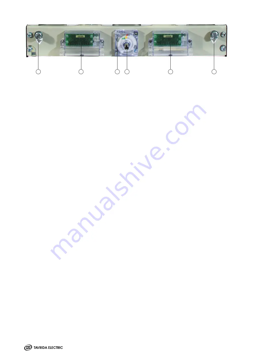
1. Earthing studs
2. ISM auxiliary switches modules (each has 3 NO and 3 NC
contacts)
3. Interlocking cables interface
(up to 2 cables can be connected)
4. Interlocking shaft
Figure 26
ISM15_LD_8, ISM15_MD_1, ISM15_HD_1 and ISM25_Shell_2 interface
1) The position indication of ISM provided by the CM can be incorrect if the CM is not operable due to an absence of auxiliary supply. The
relay keeps its state after the CM power supply disconnection. For demanding applications, conventional mechanical microswitches located
at the ISM can be used.
Summary of Contents for VCB15
Page 2: ......
Page 4: ......
Page 5: ...1 Introduction...
Page 9: ...2 Presentation...
Page 11: ...3 Product Coding...
Page 23: ...4 Technical Parameters...
Page 33: ...5 Design and Operation...
Page 42: ......
Page 43: ...6 Functionality...
Page 48: ......
Page 49: ...7 Application Notes...
Page 56: ......
Page 57: ...Appendix 1 Type Tests...
Page 61: ...Appendix 2 Withdrawable VCB Package Dimensions...
Page 63: ...Appendix 3 Overall Drawings...
Page 65: ...65 VCB15_LD8_16D 17 5kV 800 A PCD 210 mm weight 76 kg Lmax 677 mm Wmax 682 mm Hmax 528 mm...
Page 69: ...69 VCB15_MD1_16D 17 5kV 1250 A PCD 210 mm weight 74 kg Lmax 677 mm Wmax 682 mm Hmax 515 mm...
Page 73: ...73 VCB15_HD1_16D 17 5kV 2500 A PCD 275 mm weight 140 kg Lmax 656 5 mm Wmax 882 mm Hmax 704 mm...
Page 74: ...74 VCB15_HD1_16D 17 5kV 3150 A PCD 275 mm weight 158 kg Lmax 656 5 mm Wmax 882 mm Hmax 704 mm...
Page 101: ...101 3 n 3B 3B 24 kV 1250 A fixed contact 2000 A fixed contact...
Page 102: ...102 3150 A fixed contact...
Page 103: ...Appendix 4 Secondary Schemes...
Page 104: ...104 VCB15_LD8_16D with Plastic Plug...
Page 105: ...105 VCB15_LD8_16D with Metal Plug...
Page 113: ......
Page 114: ......
Page 115: ......


