background image

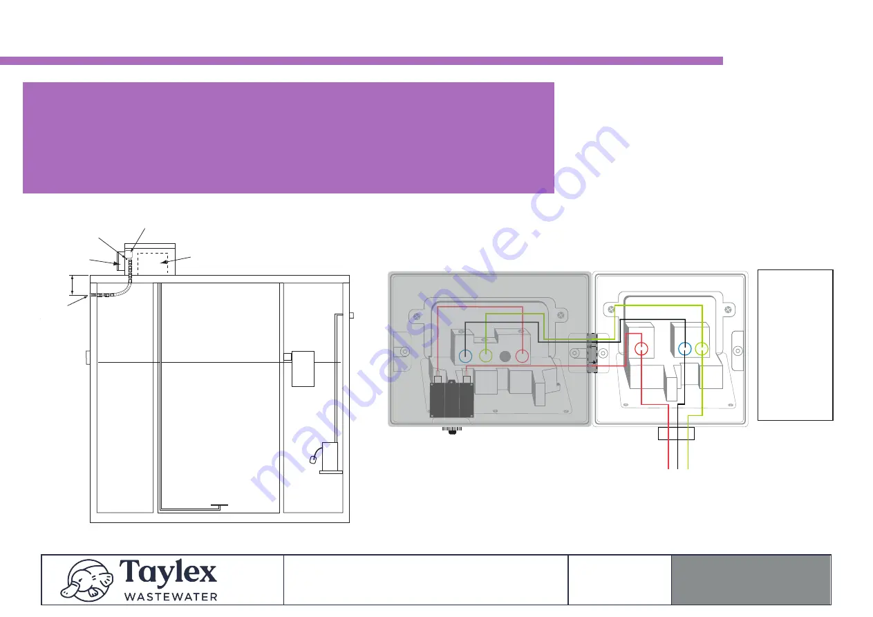
Control 

P

anel

25mm Elec

trical

Weather P

r

oof 

GPO’s

300mm

Coupling

7amp Circuit Breaker 

Reset Switch

Nitto LA80B 

Blower Box

IMPORTANT INSTRUCTIONS

• Dedicated 10amp Circuit Breaker in power board (Taylex

®

 Best Practise)

• Hardwired with 2.5mm wire (ANE) Active, Neutral, Earth to Weatherproof GPO located

in blower box

• Connect the 12V to 240V power supply plug to the single GPO

• Connect the 2 plugs (pump and blower) to the double GPO’s

• Turn all 3 GPO Switches ON

Taylex 

Electrical


Connection


Diagram


TITLE:


DATE:


Taylex 

ABS+ABSNR


01/01/2023


TAYLEX ABS+ABNSNR ELECTRICAL

CONNECTION DIAGRAM 

Electrician 

- Connect the incoming mains with the existing wires

that connect to the double GPO, ensuring the correct

polarity is maintained.

Weather Proof Single GPO

No Connection Required - 

DO NOT REMOVE

7amp Breaker 

(Pump & Blower)

EARTH


Green

/

Yellow 

Wire)


BP  Connect  with

Taylex  Earth


NEUTRAL


Black/

Blue 

Wire)


BP Connect with

Taylex Neutral

(

Blue 

Wire)

ACTIVE


Red

/

Brown 

Wire)


Connect  at  Centre

Hole of Isolator

Switch

Summary of Contents for ABS

Page 1: ...INSTALLATION MANUAL CONCRETE ADVANCED BLOWER SYSTEM ABS ABSNR...

Page 2: ...ABS Standard Lifting Instructions 9 c ABS Tall 400 Excavation Instructions 10 d ABS Tall 400 Lifting Instructions 11 e ABS Tall 600 Excavation Instructions 12 f ABS Tall 600 Lifting Instructions 13 1...

Page 3: ...EN WET During cleaning maintenance repair work the surrounding area may become extremely slippery due to spilt water Caution is to be taken when walking standing near the ABS when these activities are...

Page 4: ...oil moisture for heavy equipment access Weather conditions 5 MARK OUT To ensure the ABS is installed in the position nominated by the Home Owner Builder the location of the ABS should be marked out pr...

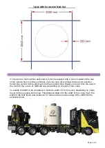
Page 5: ...n behind the vehicle before placing it into the prepared hole Maximum reach from the rear of the truck to the centre of ABS will vary depending on the size of the crane To enable the ABS to be unloade...

Page 6: ...Page 5 of 15...

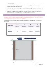
Page 7: ...cess is the responsibility of the property owner builder 7 INSTALLATION Always ensure the installation location include the future landscaping provision allow for the diversion of stormwater and surfa...

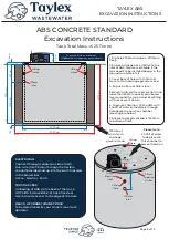
Page 8: ...ibuted layers around the tank perimeter Ensure that sand or excavated material does not fall on the lid of the ABS as this will fall into the system through the manholes and clog the system and irriga...

Page 9: ...mm drainage gravel or sand 4 Ensure bottom of hole is level 5 Back ll with soil from Excavation in no more than 500mm equally distributed layers around the tank Avoid back lling with rocks over 300mm...

Page 10: ...hrough TOP lifting holes provided in the lid of the ABS 3 Loop chains through the lifting holes directly below on the inside wall of the ABS 4 Steel reinforcing bars have been installed inside the con...

Page 11: ...distributed layers around the tank Ensure there is no backfilling with rocks over 300mm 6 To prevent flotation fill the ABS with 5 000lt of water immediately through hole above the aeration chamber s...

Page 12: ...p and blower to the double GPO s Turn all 3 GPO Switches ON Taylex Electrical Connection Diagram TITLE DATE Taylex ABS ABSNR 01 01 2023 TAYLEX ABS ABNSNR ELECTRICAL CONNECTION DIAGRAM Electrician Conn...

Reviews: