background image

Page 

of 13


1.


INTRODUCTION

The Taylex


ABS5000 Secondary Treatment System is designed to be installed both in- 

ground and above ground, collecting all wastewater from a domestic residence or

suitable commercial properties. This manual has been put together to explain the

installation process of the ABS5000 system as a guide only. Some sites may differ in

access and slope, which need to be taken into account when delivering and installing the

system

.

2.


SAFETY   INSTRUCTIONS

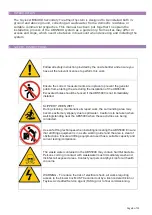
Follow all safety instruction provided by the onsite builder and ensure you 

have all the relevant licences to perform this work.


Ensure the correct measurements are in place to prevent the general 

public from entering the site during the installation of the ABS5000.


Excavated holes should be fenced if the ABS5000 is not immediately 

installed.


SLIPPERY WHEN WET!


During cleaning, maintenance & repair work, the surrounding area may 

become extremely slippery due to spilt water. Caution is to be taken when 

walking/standing near the ABS5000 when these activities are being 

conducted.


Use safe lifting techniques when installing/relocating the ABS5000. Ensure 

that all lifting equipment is in a safe working order and the area is clear of 

obstructions. Ensure all lifting equipment used has a suitable capacity and 

current testing/compliance.


The waste water contained in the ABS5000 may contain harmful bacteria. 

Persons coming in contact with wastewater must immediately wash and 

disinfect all exposed areas. Contact your personal physician for all health 

concerns.


WARNING - To reduce the risk of electrical shock, all works requiring 

access to the blower box MUST be carried out by a licenced electrician or 

Taylex

®

 Accredited Service Agent (TASA) prior to final commissioning.


Summary of Contents for ABS5000

Page 1: ...Installation Manual ADVANCED BLOWER SYSTEM 5000 ABS5000 Standard...

Page 2: ...8 9 COMMISSIONING 8 10 EXCAVATION LIFTING INSTRUCTIONS 9 a ABS5000 Excavation Instructions 9 b ABS5000 Lifting Instructions 10 11 ELECTRICAL CONNECTION DIAGRAM 11 12 Note Do not act solely on the basi...

Page 3: ...ced if the ABS5000 is not immediately installed SLIPPERY WHEN WET During cleaning maintenance repair work the surrounding area may become extremely slippery due to spilt water Caution is to be taken w...

Page 4: ...moisture for heavy equipment access Weather conditions 5 MARK OUT To ensure the ABS5000 is installed in the position nominated by the Home Owner Builder the location of the ABS5000 should be marked o...

Page 5: ...n behind the vehicle before placing it into the prepared hole Maximum reach from the rear of the truck to the centre of ABS5000 will vary depending on the size of the crane To enable the ABS5000 to be...

Page 6: ...Page 6 of 13...

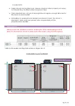
Page 7: ...n allows for the diversion of storm water and surface waters away from the system Width Height Inlet Height from bottom of tank Inlet Depth from ground level Required Base 5 7mm Drainage Gravel Sand H...

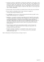
Page 8: ...inflow outflow direction 1 deviation Backfilling Use sand or excavated material spoil with maximum particle size of 300mm Backfilling of excavation to be completed in not more than 500mm equally dist...

Page 9: ...is completed prior to having the system commissioned Tanks is full of water 5 000lt each Effluent Disposal area is installed Effluent Disposal Area feed line is connected to ABS5000 Tank 2 Electrical...

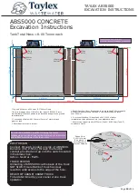
Page 10: ...13 NON TRAFFICABLE LOADS ONLY NON TRAFFICABLE LOADS ONLY 6000 mm 2425 mm 2425 mm 100mm of 5mm 7mm drainage gravel or sand 100mm of 5mm 7mm drainage gravel or sand 100mm Inlet Lifting Holes Lifting Ho...

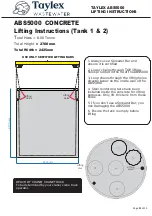
Page 11: ...ing Holes 1 Always use a Spreader Bar and ensure it is certified 2 Lower chains through TOP lifting holes provided in the lid of the ABS5000 3 Loop chains through the lifting holes directly below on t...

Page 12: ......

Page 13: ......
Reviews: