Maintenance, Service, and Repair
Batteries
Page 8
7. Remove the battery hold downs.
8. Inspect the battery hold downs for corrosion. If any signs of corrosion are seen then the
battery hold downs should be replaced.
9. Remove all battery jumpers from both posts of the battery or batteries being replaced.
NOTE: It is recommended to replace the battery jumpers when replacing
the batteries.
10. Remove the batteries from the vehicle.
11. Inspect the battery compartment for signs of corrosion.
12. If minimal signs of corrosion are seen, then the damaged paint should be stripped off and the
entire battery compartment prepped and repainted.
13. If there are excessive signs of corrosion, then it may be necessary to replace some of the
frame members or completely rebuild the battery compartment.
14. Inspect the main positive and negative cables and terminals, charger cables and terminals
and 12-volt tap wiring. If any of the terminals or wires show signs of corrosion, then they must
be repaired or replaced.
15. Install the batteries in reverse order. Refer to the
Illustrated Parts List
for battery cable
routing.
16. It is recommended to replace the battery terminal hardware when replacing the batteries.
17. Torque the terminal hardware to 7-8 ft.-lbs.
18. Tighten the hold downs so that the batteries are secure but not so tight as to deform the
batteries.
19. Remove the blocks from the wheels and test drive.
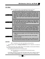
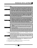
Do not leave cables on batteries that have been removed from the
vehicle. Cables left on batteries could cause a short circuit resulting
in battery explosion, severe bodily injury and/or property damage.
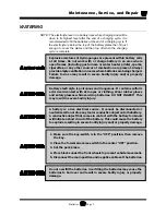
When torquing battery hardware, use a backup wrench on the battery
bolt and tighten the nut. Failure to use a backup wrench may damage
the battery post.
Summary of Contents for B 1-50
Page 2: ......
Page 6: ...TAYLOR DUNN ...
Page 14: ...Model B 1 00 ...
Page 30: ...TAYLOR DUNN ...
Page 36: ...TAYLOR DUNN ...
Page 52: ...TAYLOR DUNN ...
Page 66: ...Maintenance Service and Repair Steering Page 14 Exploded View of Steering Gear ...
Page 90: ...TAYLOR DUNN ...
Page 124: ...TAYLOR DUNN ...
Page 130: ...TAYLOR DUNN ...
Page 161: ...Wire Diagrams ...
Page 194: ...Illustrated Parts PARTS PAGE 10 Front Suspension 4 3 2 1 5 10 6 8 9 7 11 12 ...
Page 202: ...Illustrated Parts PARTS PAGE 18 Motor 2 3 5 6 4 7 8 1 9 10 Armature 9 ...
Page 206: ...Illustrated Parts PARTS PAGE 22 Wheels and Tires Ref wheel hub 1 2 5 assembly 4 3 6 7 8 9 ...
Page 208: ...Illustrated Parts PARTS PAGE 24 Instrument Panel dash ...
Page 217: ...Illustrated Parts PARTS PAGE 33 This page intentionaly left blank ...
Page 220: ...Illustrated Parts PARTS PAGE 36 Seat Cushions Deck and Lights B 1 50 ...
Page 222: ...Illustrated Parts PARTS PAGE 38 Seat Cushions Deck and Lights MX 1600 ...
Page 224: ...Illustrated Parts PARTS PAGE 40 Decals B 1 50 VIEW FROM INSIDE OF COWL 1 2 3 4 5 6 7 8 9 ...
Page 230: ...Illustrated Parts PARTS PAGE 46 Stake Sides B 1 50 1 2 3 4 5 6 7 8 ...


