Safety Rules
Page 5
SAFETY RULES AND OPERATING INSTRUCTIONS
VEHICLE CONTROLS
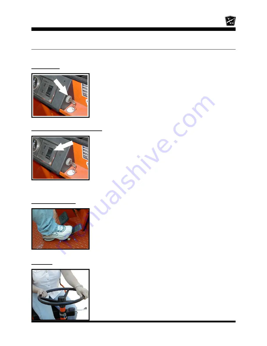
Key-Switch
A key-switch, located on the right side of the instrument panel, turns on the
vehicle. Rotate the key clockwise to turn the vehicle power on,
counterclockwise to turn the vehicle power off.
The key-switch should be in the “OFF” position whenever the operator
leaves the driver's seat.
This switch is also designed to secure and disable the vehicle. The key
can only be removed when the key-switch is in the “OFF” position.
Forward-Off-Reverse Switch
The forward-Off-reverse switch, located on the right side of the instrument
panel, determines the direction of travel of the vehicle. Push the top of the
switch to engage the forward direction. Push the bottom of the switch to
engage the reverse direction.
DO NOT SHIFT from forward to reverse or vice-versa while the vehicle is
in motion. Make sure the vehicle is completely stopped before shifting.
The forward-reverse switch should be in the center “OFF” position, with
key-switch off and the park brake set whenever the operator leaves the
driver's seat.
Accelerator Pedal
The accelerator pedal is located to the right of the brake pedal. It controls
the speed of the vehicle and operates similar to the accelerator pedal in an
automobile. Depress the pedal to increase speed and release the pedal to
decrease speed.
Steering
The steering wheel and steering system are similar to an automobile. To
turn right, turn the steering wheel clockwise. To turn left, turn the steering
wheel counter-clockwise.
Summary of Contents for B 1-50
Page 2: ......
Page 6: ...TAYLOR DUNN ...
Page 14: ...Model B 1 00 ...
Page 30: ...TAYLOR DUNN ...
Page 36: ...TAYLOR DUNN ...
Page 52: ...TAYLOR DUNN ...
Page 66: ...Maintenance Service and Repair Steering Page 14 Exploded View of Steering Gear ...
Page 90: ...TAYLOR DUNN ...
Page 124: ...TAYLOR DUNN ...
Page 130: ...TAYLOR DUNN ...
Page 161: ...Wire Diagrams ...
Page 194: ...Illustrated Parts PARTS PAGE 10 Front Suspension 4 3 2 1 5 10 6 8 9 7 11 12 ...
Page 202: ...Illustrated Parts PARTS PAGE 18 Motor 2 3 5 6 4 7 8 1 9 10 Armature 9 ...
Page 206: ...Illustrated Parts PARTS PAGE 22 Wheels and Tires Ref wheel hub 1 2 5 assembly 4 3 6 7 8 9 ...
Page 208: ...Illustrated Parts PARTS PAGE 24 Instrument Panel dash ...
Page 217: ...Illustrated Parts PARTS PAGE 33 This page intentionaly left blank ...
Page 220: ...Illustrated Parts PARTS PAGE 36 Seat Cushions Deck and Lights B 1 50 ...
Page 222: ...Illustrated Parts PARTS PAGE 38 Seat Cushions Deck and Lights MX 1600 ...
Page 224: ...Illustrated Parts PARTS PAGE 40 Decals B 1 50 VIEW FROM INSIDE OF COWL 1 2 3 4 5 6 7 8 9 ...
Page 230: ...Illustrated Parts PARTS PAGE 46 Stake Sides B 1 50 1 2 3 4 5 6 7 8 ...


