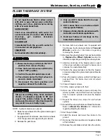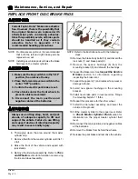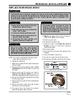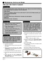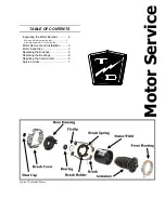
Motor Service
Motor
Page 2
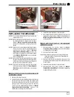
Enclosed Motors (GE, no cooling fan)
General Electric Motors
NOTE: Some motors may not have the brush
inspection holes. In this case, the motor must
be disassembled to inspect the brushes. For
future inspections, holes msy be drilled into
the motor housing after it has been
disassembled.
6. Insert a 0.035” diameter wire through the brush
inspection hole above each brush until it contacts
the top of the brush.
7. Mark the wire to indicate how far it was inserted
into the motor housing.
8. Remove the wire and measure how far into the
motor the wire was inserted.
9. If any one wire insertion length exceeds the length
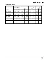
specified in
Service Limits
, then all four brushes
should be replaced. Refer to
Replacing the
Brushes
section for information regarding
replacing the motor brushes.
10. Reconnect the main positive and negative cables
at the batteries.
11. Remove the blocks from behind the wheels,
release the park brake and test drive.
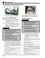
INSPECTING THE MOTOR BRUSHES
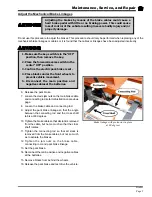
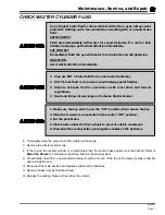
1. Make sure the key-switch is in the “OFF”
position, then remove the key.
2. Place the forward-reverse switch in the
center “OFF” position.
3. Set the park brake.
4. Place blocks under the front wheels to
prevent vehicle movement.
5. Disconnect the main positive and
negative cables at the batteries.
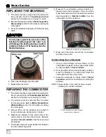
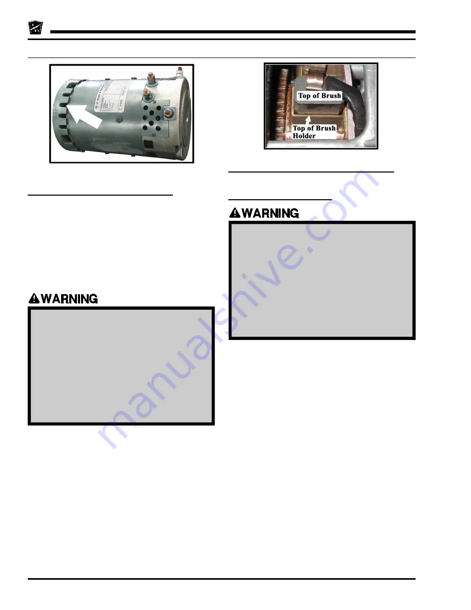
Typical motor with cooling fan indicated by
the arrow
Typical brush and brush holder
Motors with internal cooling fans
NOTE: There are four brushes in the motor. The
brushes will not wear at the same rate. It is
recommended that all four brushes are
inspected at the same time.
NOTE: In some vehicle configurations it may not be
possible to inspect all four brushes while the
motor is in the vehicle. Refer to
Transmission Service
section for
information on removing the motor.
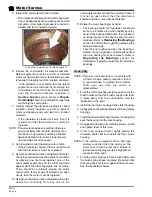
6. Look through the brush cover and compare the
top of the brush to the top of the brush holder. If it
is even with or below the top of the brush holder
then the brushes should be removed and
measured. Refer to
Replacing the Brushes
section for information regarding removing the
motor brushes.
7. If any one brush is less than or equal to the service
limit specified in
Service Limits
, then all four
brushes should be replaced.
8. Reconnect the main positive and negative cables
at the batteries.
9. Remove the blocks from behind the wheels,
release the park brake and test drive.
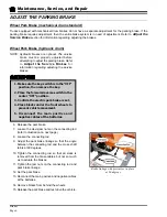
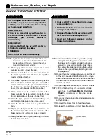
1. Make sure the key-switch is in the “OFF”
position, then remove the key.
2. Place the forward-reverse switch in the
center “OFF” position.
3. Set the park brake.
4. Place blocks under the front wheels to
prevent vehicle movement.
5. Disconnect the main positive and
negative cables at the batteries.
Summary of Contents for B 1-50
Page 2: ......
Page 6: ...TAYLOR DUNN ...
Page 14: ...Model B 1 00 ...
Page 30: ...TAYLOR DUNN ...
Page 36: ...TAYLOR DUNN ...
Page 52: ...TAYLOR DUNN ...
Page 66: ...Maintenance Service and Repair Steering Page 14 Exploded View of Steering Gear ...
Page 90: ...TAYLOR DUNN ...
Page 124: ...TAYLOR DUNN ...
Page 130: ...TAYLOR DUNN ...
Page 161: ...Wire Diagrams ...
Page 194: ...Illustrated Parts PARTS PAGE 10 Front Suspension 4 3 2 1 5 10 6 8 9 7 11 12 ...
Page 202: ...Illustrated Parts PARTS PAGE 18 Motor 2 3 5 6 4 7 8 1 9 10 Armature 9 ...
Page 206: ...Illustrated Parts PARTS PAGE 22 Wheels and Tires Ref wheel hub 1 2 5 assembly 4 3 6 7 8 9 ...
Page 208: ...Illustrated Parts PARTS PAGE 24 Instrument Panel dash ...
Page 217: ...Illustrated Parts PARTS PAGE 33 This page intentionaly left blank ...
Page 220: ...Illustrated Parts PARTS PAGE 36 Seat Cushions Deck and Lights B 1 50 ...
Page 222: ...Illustrated Parts PARTS PAGE 38 Seat Cushions Deck and Lights MX 1600 ...
Page 224: ...Illustrated Parts PARTS PAGE 40 Decals B 1 50 VIEW FROM INSIDE OF COWL 1 2 3 4 5 6 7 8 9 ...
Page 230: ...Illustrated Parts PARTS PAGE 46 Stake Sides B 1 50 1 2 3 4 5 6 7 8 ...


