Steering
Page 49
MB-150-03
B0-015-00 and MX-016-00
REPLACE STEERING SHAFT
1: If equipped with a horn switch in the steering
wheel, remove the switch, disconnect the wires
from the switch and cut the terminals off of the
wires.
2: Remove the steering wheel. Refer to Replace
the Steering Wheel procedure for information
regarding removing the steering wheel.
3: Remove the upper steering shaft bushing or
bearing from the steering column.
4: Remove the steering gear access cover from the
steering column (if equipped).
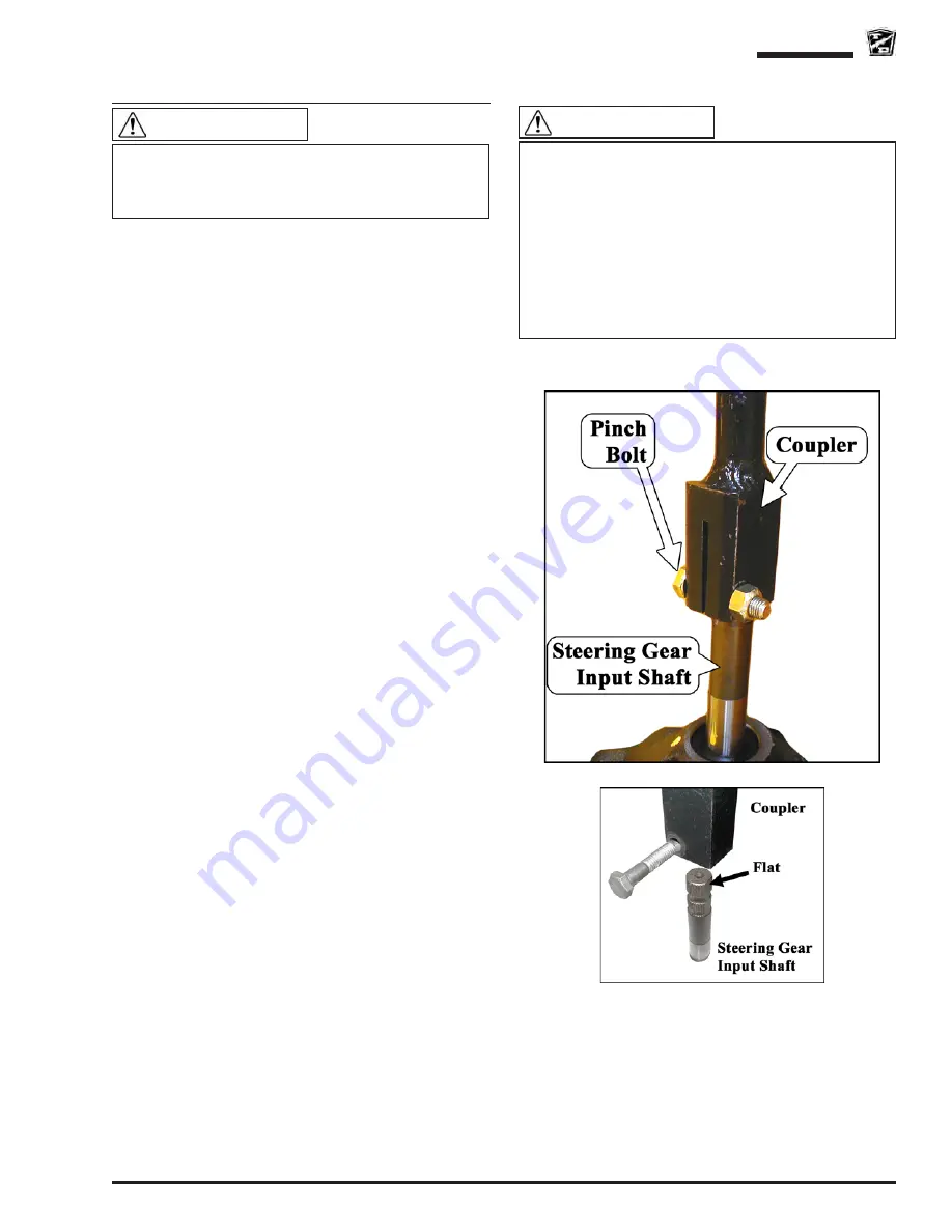
5: Remove and discard the pinch bolt and nut from
the steering shaft coupler.
Note: Most vehicle configurations will now allow
the steering shaft to slide off of the steering
gear input shaft and then back down out of
the steering column. If there is not enough
clearance for this procedure then the
steering gear must be removed. Refer to
Replace the Steering Gear for information
regarding removing the steering gear.
6: Remove the steering shaft from the vehicle.
7: Lightly grease the input shaft splines, steering
wheel splines and the upper steering shaft
bushing.
8: Install the steering shaft in reverse order using
a new pinch bolt. Orientate the shaft so that the
pinch bolt is opposite the flat in the steering gear
shaft. See the illustration to the right.
9: Tighten the pinch bolt per torque listed in the
Hardware Torque table at the end of this section.
10: Reconnect the main positive and negative cables
at the batteries.
11: Remove the blocks from behind the wheels.
12: Release the parking brake and test drive.
This section is one section of a complete service
manual. Before starting any procedure, read all
warnings and instructions that are located in the
Service Guidelines chapter.
WARNING
Do not use the original pinch bolt and nut. Failure to
replace the pinch bolt and nut may result in failure of
the steering causing loss of control of the vehicle. This
could lead to severe bodily injury and/or property
damage.
Make sure that the pinch bolt is not aligned with the
flat on the steering shaft. Aligning the bolt with the
flat could result in failure of the steering and loss of
control of the vehicle. This could lead to severe bodily
injury and/or property damage.
WARNING
Summary of Contents for B0-150-00
Page 6: ......
Page 12: ...Page 12 MB 150 03 Introduction B0 015 00 and MX 016 00 Notes...
Page 20: ...PM Schedule Page 20 B0 015 00 and MX 016 00 MB 150 03 Notes...
Page 21: ...Table of Contents Special Tool List Special Tool List Tool List 22 Troubleshooting Guide 23...
Page 24: ...Tool List Page 24 B0 150 00 and MX 016 00 MB 150 03 Notes...
Page 27: ...Lubrication Page 27 MB 150 03 B0 150 00 and MX 016 00 LUBRICATION DIAGRAM...
Page 28: ...Lubrication Page 28 B0 015 00 and MX 016 00 MB 150 03 Notes...
Page 36: ...Front Axle Page 36 B0 150 00 and MX 016 00 MB 150 03 Notes...
Page 53: ...Steering Page 53 MB 150 03 B0 015 00 and MX 016 00 Exploded View of Steering Gear...
Page 72: ...Drive Motor Page 72 B0 015 00 and MX 016 00 MB 150 03 Notes...
Page 78: ...Tires Wheels Page 78 B0 015 00 and MX 016 00 MB 150 03 Notes...
Page 104: ...Replacement Parts Page 104 MB 150 03 B0 015 00 and MX 016 00 TRANSAXLE ASSEMBLY...
Page 116: ...Replacement Parts Page 116 MB 150 03 B0 015 00 and MX 016 00 FRAME AND BODY CAB...
Page 119: ...Replacement Parts Page 119 Not available at time of printing MB 150 03 B0 015 00 and MX 016 00...
Page 120: ...Replacement Parts Page 120 MB 150 03 B0 015 00 and MX 016 00 LINKAGE THROTTLE AND BRAKE...
Page 134: ...Replacement Parts Page 134 MB 150 03 B0 015 00 and MX 016 00 Notes...


