Safety Rules
Page 15
SAFETY RULES AND OPERATING INSTRUCTIONS
Lestronic II
®
Charger Operation
The Lestronic II
®
charger is a semiautomatic charging system. The charger
will turn itself ON when the AC power cord is connected to the AC power
source and turn itself OFF when the batteries are fully charged. Refer to the
data plate on the charger for the voltage and type power required for the
charger.
When the charger is plugged in, it should turn on within a few seconds. To
determine if the charger is on, listen for a humming sound from the charger.
If the charger does not turn on, then there may be a fault in the AC line
voltage or in the charger. Refer troubleshooting to a qualified technician.
Typical charging times are eight to twelve hours depending on the how deep the batteries are discharged.
Charging times exceeding 16-hours may be a result of faulty batteries, faulty charger, noisy or fluctuating
AC line voltage, or momentarily interrupting the charging cycle. Refer troubleshooting to a qualified
technician.
Typical Lestronic II
®
Built In
Signet Charger Operation, Model HB Series
The Signet
®
HB series chargers use a semi-automatic charging system. The
charger will turn itself ON when the AC power cord is connected to the AC power
source and turn itself OFF when the batteries are fully charged. Refer to the data
plate on the charger for the voltage and type power required for the charger.
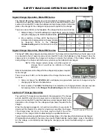
There is a series of LED’s on the faceplate of the charger that serve two functions:
1. Status of charge. The LED’s will display an approximate percent of charge
during the charging cycle. Refer to the table below.
2. Error condition. All three LED’s flashing is an
indication of a charging problem (charger will also
be beeping). Refer to the
Charger
Troubleshooting
section for information on error
codes.
Signet Charger Operation, Model HBS series
The Signet
®
HBS series chargers are fully automatic. The charger will turn itself ON when the AC power cord
is connected to the AC power source and turn itself OFF when the batteries are fully charged. Once the
charge cycle is complete, the charger will continue to monitor the batteries. If the battery voltage drops
during storage, the charger will start a new cycle to keep the batteries fully charged.
NOTE: If the charger restarts during a short time period of
storage, then it would be an indication of faulty
batteries.
Refer to the data plate on the charger for the voltage and type power required
for the charger.
There is a series of LED’s on the faceplate of the charger that serve two
functions:
1. Status of charge. The
STATUS
LED’s will display an approximate percent of charge during the
charging cycle. Refer to the table below.
2. Error condition. The
FAULT
LED flashing is an indication of a charging problem (charger may also
be beeping). Refer to the
Charger Troubleshooting
section for information on error codes.
Charging State
LED1
LED2
LED3
0 to 50%
Blinking
OFF
OFF
50% to 75%
ON
Blinking
OFF
75% to 100%
ON
ON
Blinking
Cycle complete
ON
ON
ON
Summary of Contents for B0-248-48AC
Page 2: ......
Page 70: ...Maintenance Service and Repair Steering Page 22 Exploded View of Steering Gear...
Page 88: ...TAYLOR DUNN...
Page 114: ...TAYLOR DUNN...
Page 120: ...TAYLOR DUNN...
Page 132: ...TAYLOR DUNN...
Page 134: ...TAYLOR DUNN...
Page 164: ...Illustrated Parts Parts Page 2 Front Axle...
Page 166: ...Illustrated Parts Parts Page 4 Steering Knuckle...
Page 168: ...Illustrated Parts Parts Page 6 Steering Linkage...
Page 174: ...Illustrated Parts Parts Page 12 Rear Suspension View from rear...
Page 176: ...Illustrated Parts Parts Page 14 Transmission Gear Case...
Page 180: ...Illustrated Parts Parts Page 18 Rear Brakes Front Brakes...
Page 182: ...Illustrated Parts Parts Page 20 Brake Lines Master Cylinder...
Page 184: ...Illustrated Parts Parts Page 22 Motor...
Page 186: ...Illustrated Parts Parts Page 24 Motor Mount Apply 94 421 34 grease to inside of motor coupler...
Page 188: ...Illustrated Parts Parts Page 26 Wheels and Tires Ref wheel hub 1 2 5 assembly 4 3 6 7 8 9 10...
Page 196: ...Illustrated Parts Parts Page 34 Lighting Stobe Light 4 1 2 3 5 6 7...
Page 206: ...Illustrated Parts Parts Page 44 Seat Cushions and Deck...
Page 208: ...Illustrated Parts Parts Page 46 Mirrors 92 202 00 Assembly Miscellaneous Frame Components...
Page 210: ...Illustrated Parts Parts Page 48 Decals...
Page 212: ...Illustrated Parts Parts Page 50 Cab Options Steel Cab Fiberglass cab...
Page 218: ...Illustrated Parts Parts Page 56 Hydraulic Dump Body Option...
Page 220: ...Illustrated Parts Parts Page 58 Rear Cargo Box 1 2 3 4 5 6 5 Top Covers...
Page 222: ...Illustrated Parts Parts Page 60 Hitches...
Page 224: ...TAYLOR DUNN...


