Maintenance, Service, and Repair
F2/F3 Transmission
Page 6
Assemble
1. Thoroughly clean all gasket surfaces.
2. Apply a 1/8” bead of 94-430-03 gasket sealer to
the face of the 3rd member.
3. Install the backing plate to the 3rd member. Torque
to 30-45 ft-lbs.
4. Install the motor to the backing plate. Do not fully
tighten the motor mounting hardware at this time.
5. Install the motor sprocket, drive sprocket and
chain. Do not adjust the chain tension at this time.
6. Apply a 1/8” bead of 94-430-03 gasket sealer to
the chain case housing.
7. Install the chain case centering tool (refer to
Appendix A) into the pinion seal bore in the chain
case housing.
CHAIN CASE
NOTE: Some vehicle configurations may require that
the transmission be removed to disassemble
the chain case. Refer to section
Transmission Assembly
for information
on removing the transmission.
Disassemble
6. Place an oil drain pan under the chain case.
7. Remove the chain case drain plug and allow all of
the oil to drain from the housing and then reinstall
the drain plug
8. Remove the brake drum. Refer to section
Brakes: Replace the Brake Drum
for
information regarding removing the brake drum.
9. Remove the nuts from the three threaded studs at
the small end of the chain case housing.
10. Remove the chain case housing bolts, brake
assembly, and alignment brackets.
11. Remove the chain case housing from the backing
plate.
12. Remove the pinion seal from the chain case
housing.
13. Loosen the motor mounting bolts.
14. Loosen the chain adjuster.
15. Remove the drive chain, motor nut and sprocket
and the drive sprocket.
16. If the backing plate must be removed from the
3rd member, first remove the motor from the
backing plate then remove the backing plate from
the 3rd member.
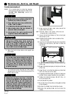
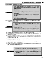
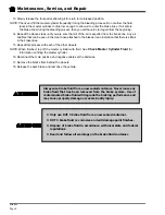
1. Make sure the key-switch is in the “OFF”
position, then remove the key.
2. Place the forward-reverse switch in the
center “OFF” position.
3. Set the park brake.
4. Place blocks under the front wheels to
prevent vehicle movement.
5. Disconnect the main positive and
negative cables at the batteries.
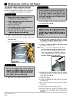
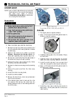
Typical Chain Case
Pinion brake shown is not used on the ET-150
Apply sealer around the ID of the holes
Summary of Contents for ET-015-00
Page 2: ......
Page 14: ...TAYLOR DUNN...
Page 28: ...TAYLOR DUNN...
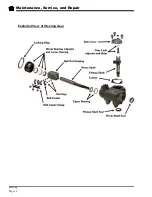
Page 48: ...Maintenance Service and Repair Steering Page 12 Exploded View of Steering Gear...
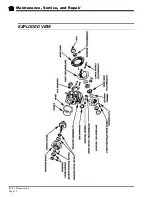
Page 60: ...Maintenance Service and Repair F2 F3 Transmission Page 12 EXPLODED VIEW...
Page 71: ...Maintenance Service and Repair Brakes Page 11 Rear Brake left side shown...
Page 72: ...TAYLOR DUNN...
Page 80: ...TAYLOR DUNN...
Page 90: ...TAYLOR DUNN...
Page 94: ...TAYLOR DUNN...
Page 100: ...TAYLOR DUNN...
Page 114: ...TAYLOR DUNN...
Page 116: ...TAYLOR DUNN...
Page 130: ...Illustrated Parts Parts Page 14 Rear Axle Axle tube 4 5 6 7 3 2 Rear Brakes...
Page 132: ...Illustrated Parts Parts Page 16 Rear Suspension 1 2 3 4 5 6 7 8 9 10 11 12 13 14 Drive Shaft...
Page 134: ...Illustrated Parts Parts Page 18 Motor direct drive Motor Mount direct drive...
Page 142: ...Illustrated Parts Parts Page 26 Instrument Panel dash...
Page 144: ...Illustrated Parts Parts Page 28 Speed Control Panel 1 2 3 4 5 6 7 8 9 10 11 12 4...
Page 152: ...Illustrated Parts Parts Page 36 Charger 2 1 15 12 11 4 3 5 8 10 6 7 9 13 14 16...

