Maintenance, Service, and Repair
Steering
Page 7
Reassembly
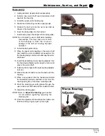
1. Lightly lubricate all parts before reassembly.
2. Install a new worm shaft seal and pitman shaft
seal into the housing.
3. Install the upper worm bearing cup.
4. Divide the ball bearing into two equal groups.
5. Position the ball nut onto the worm as shaft as
shown in the illustration.
6. Insert the ball guides into the ball nut.
7. Insert each group of bearings into the ball guides.
NOTE: Do not rotate the worm shaft while installing
the bearings. This may cause one or more
of the bearings to enter the crossover
passage in the ball nut, causing improper
operation.
8. Install the ball guide clamp.
9. Place the upper worm bearing on the worm shaft
and install the worm shaft/ball nut assembly into
the housing being careful not to damage the worm
shaft seal.
10. Install the assembled worm bearing adjuster into
the housing and tighten just enough to remove all
play in the worm shaft.
11. Install, but do not tighten the worm bearing adjuster
lock nut.
12. Rotate the worm shaft to center the ball nut in the
housing.
13. Place a new gasket onto the housing and install
the assembled pitman shaft/side cover onto the
housing using two of the three mounting bolts.
14. Pack the steering gear with grease through the
open side cover bolt hole and then install the bolt.
15. Adjust the steering gear.
NOTE: Refer to
Adjust the Steering
gear section
for information regarding adjusting the
steering gear.
16. Once the adjustments are completed, make sure
that the locking ring and jam nut are tight.
Summary of Contents for MB-238-00
Page 2: ......
Page 6: ...TAYLOR DUNN...
Page 28: ...TAYLOR DUNN...
Page 44: ...Maintenance Service and Repair Steering Page 8 Exploded View of Steering Gear...
Page 64: ...TAYLOR DUNN...
Page 112: ...TAYLOR DUNN...
Page 149: ...TABLE OF CONTENTS Wire Diagrams Complete Vehicle 2...
Page 158: ...Illustrated Parts Parts Page 8 Transmission Gear Case...
Page 162: ...Illustrated Parts Parts Page 12 Rear Brakes Brake Body Assembly...
Page 166: ...Illustrated Parts Parts Page 16 Brake Lines Illustration not available...
Page 168: ...Illustrated Parts Parts Page 18 Motor...
Page 170: ...Illustrated Parts Parts Page 20 Wheels and Tires Ref wheel hub 1 2 3 Rear Suspension...
Page 172: ...Illustrated Parts Parts Page 22 Speed Control Panel Instrument Panel dash...
Page 182: ...Illustrated Parts Parts Page 32 Seat Cushions Deck and Lights Frame Illustration not available...
Page 184: ...Illustrated Parts Parts Page 34 Decals...

