Maintenance, Service, and Repair
Brakes
Page 17
REPLACE THE MASTER CYLINDER
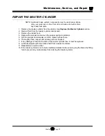
NOTE: Most vehicle configurations do not require lifting the vehicle to
remove the master cylinder. Lifting the vehicle may not be required.
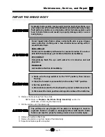
6. If required, raise the vehicle and support with jack stands.
7. Place a drain pan under the master cylinder.
8. Disconnect the brake line(s) to the master cylinder and pump out the fluid in the master cylinder
by depressing the pedal several times.
9. Remove the master cylinder bolts and remove the master cylinder from the vehicle.
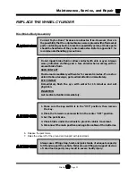
Do not ingest brake fluid or allow contact with skin or eyes. Always
wear protective clothing and a face shield when working with or
around brake fluid.
SKIN CONTACT
Flush area immediately with water for several minutes. If a rash or
skin irritation develops, get medical attention immediately.
EYE CONTACT
Immediately flush the eye with water for 15 minutes and call
physician.
INGESTION
Get medical attention immediately.
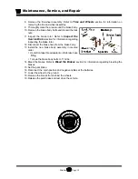
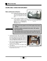
1. Make sure the key-switch is in the “OFF” position, then remove
the key.
2. Place the forward-reverse switch in the center “OFF” position.
3. Set the park brake.
4. Place blocks under the rear wheels to prevent vehicle movement.
5. Disconnect the main positive and negative cables at the batteries.
Always use a lifting strap, hoist, and jack stands, of adequate capacity
to lift and support the vehicle. Failure to use lifting and support devices
of rated load capacity may result in severe bodily injury.
Summary of Contents for MB-238-00
Page 2: ......
Page 6: ...TAYLOR DUNN...
Page 28: ...TAYLOR DUNN...
Page 44: ...Maintenance Service and Repair Steering Page 8 Exploded View of Steering Gear...
Page 64: ...TAYLOR DUNN...
Page 112: ...TAYLOR DUNN...
Page 149: ...TABLE OF CONTENTS Wire Diagrams Complete Vehicle 2...
Page 158: ...Illustrated Parts Parts Page 8 Transmission Gear Case...
Page 162: ...Illustrated Parts Parts Page 12 Rear Brakes Brake Body Assembly...
Page 166: ...Illustrated Parts Parts Page 16 Brake Lines Illustration not available...
Page 168: ...Illustrated Parts Parts Page 18 Motor...
Page 170: ...Illustrated Parts Parts Page 20 Wheels and Tires Ref wheel hub 1 2 3 Rear Suspension...
Page 172: ...Illustrated Parts Parts Page 22 Speed Control Panel Instrument Panel dash...
Page 182: ...Illustrated Parts Parts Page 32 Seat Cushions Deck and Lights Frame Illustration not available...
Page 184: ...Illustrated Parts Parts Page 34 Decals...


