Maintenance, Service, and Repair
Transmission
Page 10
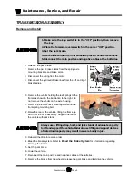
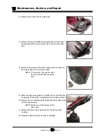
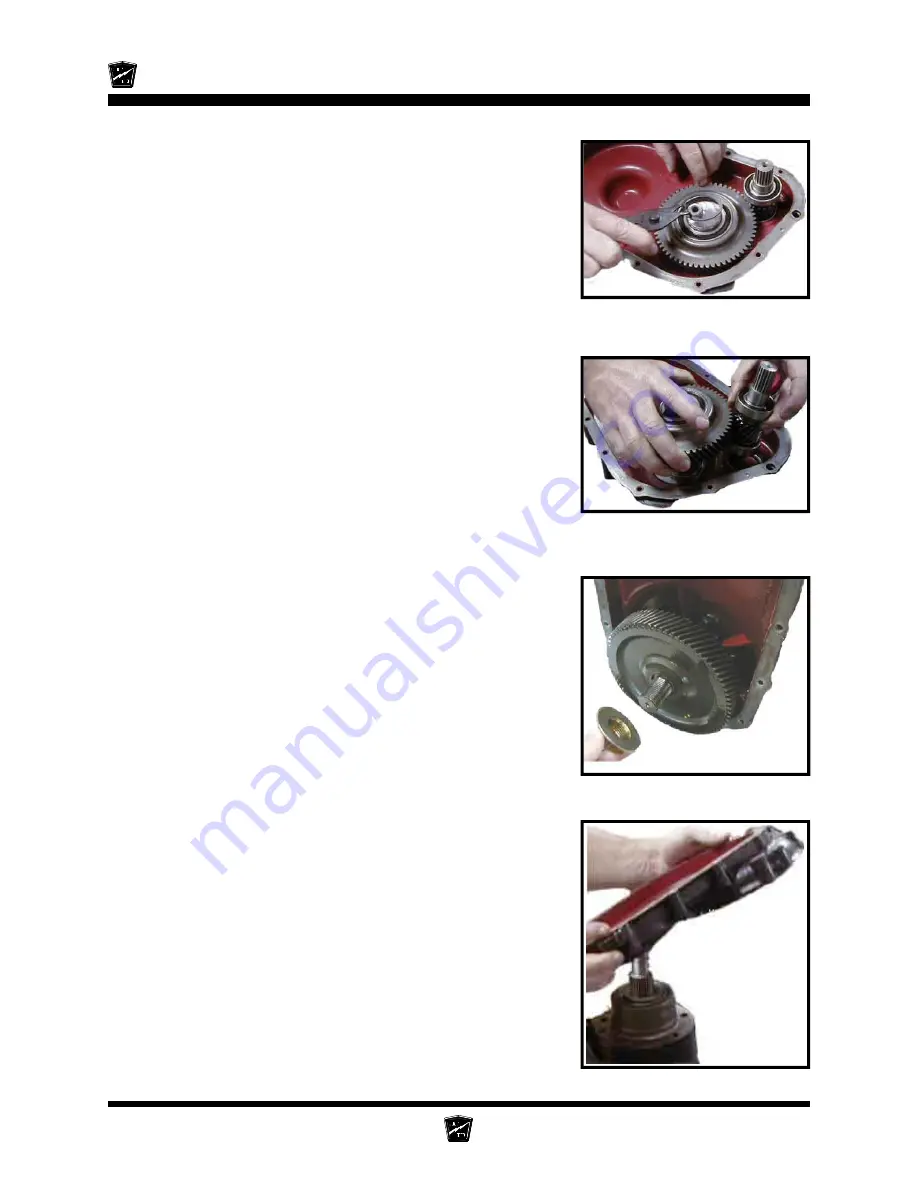
12. Remove the circlip from the idler gear.
13. Remove the input shaft/bearing assembly and idler gear/
bearing assembly from the gear case cover at the same
time.
14. Remove the pinion nut from the output gear and remove
the output gear from the pinion shaft.
NOTE: If necessary, remove the seal
from the input shaft bore at this
time.
15. Mark the gear case position in relation to the 3rd member
housing so that it will be reassembled in the same position.
16. Remove the six retaining bolts holding the gear case to the
3rd member housing.
NOTE: Make note of the angle of the
gear case.
17. Remove the gear case housing from the 3rd member
housing.
18. Inspect all parts for signs of wear or damage.
Summary of Contents for MB-238-00
Page 2: ......
Page 6: ...TAYLOR DUNN...
Page 28: ...TAYLOR DUNN...
Page 44: ...Maintenance Service and Repair Steering Page 8 Exploded View of Steering Gear...
Page 64: ...TAYLOR DUNN...
Page 112: ...TAYLOR DUNN...
Page 149: ...TABLE OF CONTENTS Wire Diagrams Complete Vehicle 2...
Page 158: ...Illustrated Parts Parts Page 8 Transmission Gear Case...
Page 162: ...Illustrated Parts Parts Page 12 Rear Brakes Brake Body Assembly...
Page 166: ...Illustrated Parts Parts Page 16 Brake Lines Illustration not available...
Page 168: ...Illustrated Parts Parts Page 18 Motor...
Page 170: ...Illustrated Parts Parts Page 20 Wheels and Tires Ref wheel hub 1 2 3 Rear Suspension...
Page 172: ...Illustrated Parts Parts Page 22 Speed Control Panel Instrument Panel dash...
Page 182: ...Illustrated Parts Parts Page 32 Seat Cushions Deck and Lights Frame Illustration not available...
Page 184: ...Illustrated Parts Parts Page 34 Decals...


