Brakes
Page 61
MR-380-03
R-380 DC System
REBUILD DISC BRAKE BODY
This procedure assumes that the component has been
removed from the vehicle. Refer to the component
assembly removal instructions for details and warnings
regarding the removal and installation procedure.
1: Pull the pistons out of the brake body.
2: Remove the piston rubber boot.
3: Remove the piston o-ring from inside of the brake
body.
4: Inspect and replace parts as required.
5:
Lubricate the brake parts with clean brake fluid
from a sealed container.
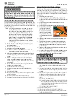
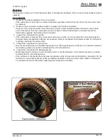
6: Install the O-rings into the brake body. Make sure
that the O-rings are installed into the second
groove and that they are not twisted (Fig 1).
7: Using tool #41-350-13 (optional), slide the rubber
boots onto the pistons as shown. The boot should
be hanging off of the end of the piston (Fig 2).
8: Insert the rubber boot/piston into the brake body
making sure that the boot is properly seated in
the groove (Fig 3).
9: Press the pistons all the way down into the brake
body making sure that the boot seats properly
into the upper groove on the piston.
10:
Install any fittings or plugs that were removed
from the brake body using teflon tape thread
sealant.
11: If the brake body assembly is not to be
immediately installed onto a vehicle, plug
the brake hose fitting hole to prevent any
contaminates from entering the brake body.
This section is one section of a complete service
manual. Before starting any procedure, read all
warnings and instructions that are located in the
Service Guidelines chapter.
WARNING
The pistons are very fragile. If the piston is damaged
it must be replaced. Failure to replace a damaged
piston could lead to brake failure and result in
property damage and/or severe bodily injury.
WARNING
Figure 1
Figure 2
Figure 3
Summary of Contents for R0-380-36
Page 6: ......
Page 12: ...Page 12 MR 380 03 Introduction R 380 DC System Notes...
Page 21: ...Table of Contents Special Tool List Special Tool List Troubleshooting Guide 23...
Page 24: ...Tool List Page 24 R 380 DC System MR 380 03 Notes...
Page 27: ...Lubrication Page 27 MR 380 03 R 380 DC System LUBRICATION DIAGRAM...
Page 28: ...Lubrication Page 28 R 380 DC System MR 380 03 Notes...
Page 44: ...Drive Axle Page 44 R 380 DC System MR 380 03 Notes...
Page 53: ...Steering Page 53 MR 380 03 R 380 DC System Exploded View of Steering Gear...
Page 72: ...Drive Motor Page 72 R 380 DC System MR 380 03 Notes...
Page 90: ...Tires Wheels Page 90 R 380 DC System MR 380 03 Notes...
Page 102: ...Replacement Parts Page 102 MR 380 03 R 380 DC System AXLE ASSEMBLY FRONT...
Page 104: ...Replacement Parts Page 104 MR 380 03 R 380 DC System AXLE REAR...
Page 106: ...Replacement Parts Page 106 MR 380 03 R 380 DC System BATTERY...
Page 108: ...Replacement Parts Page 108 MR 380 03 R 380 DC System BRAKES BRAKE LINES...
Page 114: ...Replacement Parts Page 114 MR 380 03 R 380 DC System BRAKES PARK BRAKE LINKAGE...
Page 118: ...Replacement Parts Page 118 MR 380 03 R 380 DC System CAB DOORS...
Page 136: ...Replacement Parts Page 136 MR 380 03 R 380 DC System STEERING LINKAGE...
Page 142: ...Replacement Parts Page 142 MR 380 03 R 380 DC System Notes...
Page 143: ......


