SAFETY RULES AND OPERATING INSTRUCTIONS
Safety Rules
Page 7
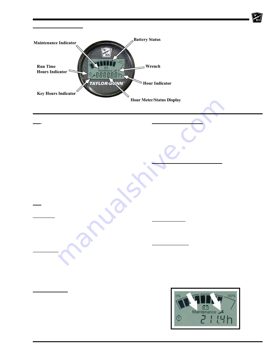
Smart View Display
Display showing Maintenance and
Wrench icons
BSI
: A bar graph representing the current state of charge
is located across the top of the display. When the
batteries are fully charged, all segments of the bar graph
will be on. As the batteries are used, segments will turn
off in the order of right to left.
When the batteries are discharged to 75%, the last three
segments will flash indicating that you are approaching
the end of the battery cycle. At this time, the vehicle’s
batteries should be charged as soon as possible.
At 90%, all segments will flash and the vehicles speed
will be reduced. At this time, the vehicle should be
removed from service for charging. Discharging beyond
90% will result in damage to the batteries that will shorten
the battery life-span.
HM:
There are three hour meter functions, Key Hours,
Run Time Hours, and Pump Hours.
Key Hours: Accumulated length of time in hours that the
key switch is in the “ON” position. When the display is
turned on, the Key Hours will be displayed for
approximately 5-seconds as indicated by the Key Hours
Indicator located at the lower left of the display. The
icon represents the silhouette of a key.
Pump hours: Accumulated length of time the hydraulic
pump has been in operation. This is an optional feature.
After the Key Hours, the Pump Hours will be displayed
for approximately 5-seconds as indicated by the Pump
Hours Indicator located at the lower left of the display.
The icon represents a motor symbol with a “P” in the
center.
Run Time Hours: Accumulated length of time that the
vehicles has been in operation. Time is accumulated
when the FS-1 switch in the accelerator module is closed.
After the Pump Hours, the Run Time Hours will be
displayed as indicated by the Run Time Hours Indicator
located at the left of the display. The icon represents a
motor symbol with a “T” in the center.
Speed controller status:
The display will indicate a fault
code whenever the control system logic detects a
problem with the control system. A fault code is being
displayed whenever the Fault Code Indicator (the letter
“F”) is visible at the left of the numeric display. Refer to
the table on the following page for a list of fault codes
and their descriptions.
Maintenance monitor (optional):
Operation: The SVD notifies the operator 10-hours
(standard) before a scheduled maintenance is due.
During this warning period, the meter will continue to
alert the operator. This should allow sufficient time for
the operator to schedule the maintenance that is due,
with minimal down time. If the scheduled maintenance
is not performed before the warning period elapses, then
the vehicles maximum speed will be significantly
reduced.
Warning period: The warning period starts when the
Maintenance Indicator is ON and the Wrench icon is
flashing. The Wrench icon will continue to flash until the
warning time has expired.
Maintenance Due: Once the warning period has expired
and the maintenance is due, the Wrench icon will stop
flashing and remain ON. Additionally, the vehicles
maximum speed will be significantly reduced until the
maintenance is performed and the display is reset. The
display should only be reset by an authorized technician.
Refer to the
Illustrated parts
section for information
regarding tools required to reset the Smart View Display.
The Smart View Display (SVD) functions as a
Battery Status Indicator (BSI), Hour Meter (HM),
speed controller status monitor, and as an optional
maintenance monitor feature. The operation of
each of these functions is listed below.
Summary of Contents for TT-316-36
Page 2: ......
Page 6: ...TAYLOR DUNN...
Page 12: ...TAYLOR DUNN...
Page 28: ...TAYLOR DUNN...
Page 76: ...TAYLOR DUNN...
Page 82: ...TAYLOR DUNN...
Page 96: ...TAYLOR DUNN...
Page 99: ...Sevcon Troubleshooting Page 3 Electrical Troubleshooting Identifying Your Controller...
Page 120: ...TAYLOR DUNN...
Page 134: ...TAYLOR DUNN...
Page 138: ...Illustrated Parts Page 2 Front Fork...
Page 140: ...Illustrated Parts Page 4 Front Brakes...
Page 142: ...Illustrated Parts Page 6 Tilt Steering Column and Gear...
Page 146: ...Illustrated Parts Page 10 Transmission Differential Case Rear Axle...
Page 148: ...Illustrated Parts Page 12 Rear Brakes Master Cylinder 8 Brake Body...
Page 150: ...Illustrated Parts Page 14 Rear Suspension...
Page 152: ...Illustrated Parts Page 16 Motor...
Page 156: ...Illustrated Parts Page 20 Brake Lines...
Page 158: ...Illustrated Parts Page 22 Wheels and Tires Ref wheel hub 1 2 5 assembly 4 3 6 7 8 9 10...
Page 164: ...Illustrated Parts Page 28 Miscellaneous Frame and Body...
Page 168: ...Illustrated Parts Page 32 Decals...
Page 172: ...TAYLOR DUNN...


