12
Model 161
Important: To the Operator
130703
WASH Key
When the WASH key is pressed, the light comes on.
This indicates beater motor operation. The STANDBY
or AUTO mode must be cancelled first to activate the
WASH mode.
AUTO Key
When the AUTO key is pressed, the light comes on.
This indicates that the main refrigeration system has
been activated. In the AUTO mode, the WASH or
STANDBY functions are automatically cancelled. The
MIX REF function is automatically locked in to
maintain the temperature of the mix in the mix hopper.
Note:
An indicating light and an audible tone will
sound whenever a mode of operation has been
pressed. To cancel any function, press the key again.
The light and mode of operation will shut off.
Indicator Light - MIX LOW
Located on the front of the machine is a mix level
indicating light. When the light is flashing, it indicates
that the mix hopper has a low supply of mix and should
be refilled as soon as possible. Always maintain at
least 3” (76 mm) of mix in the hopper. If you neglect to
add mix, a freeze- up may occur. This will cause
eventual damage to the beater, blades, drive shaft,
and freezer door.
Reset Button
The reset button is located on the front of the unit. The
reset protects the beater motor from an overload
condition. If an overload occurs, the reset mechanism
will trip. To properly reset the freezer, press the AUTO
key to cancel the cycle. Turn the power switch to the
OFF position. Wait two or three minutes and then
press the reset button firmly.
Warning: Do not use metal objects to
press the reset button. Failure to comply may
result in severe personal injury or death.
Turn the power switch to the ON position. Press the
WASH key and observe the freezer’s performance. If
the beater motor is turning properly, press the WASH
key to cancel the cycle. Press the AUTO key on both
sides of the unit to resume normal operation. If the
freezer shuts down again, contact an authorized
service technician.
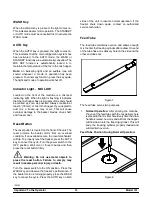
Feed Tube
The feed tube maintains overrun and allows enough
mix to enter the freezing cylinder after a draw. One end
of the tube has a mix delivery hole on the side and the
other end does not.
Figure 7
The feed tube serves two purposes.
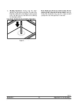
1.
Normal Operation:
After priming the machine,
the end of the feed tube with the mix delivery hole
is placed in the mix inlet hole. Every time the draw
handle is raised, new mix and air from the hopper
will flow down into the freezing cylinder. This will
keep the freezing cylinder properly loaded and
will maintain overrun.
Feed Tube Position During Normal Operation:
Figure 8


