background image

OPERATING PROCEDURES

6-7 

Models C001 and C002 

Operating Procedures 

 6

3. While the solution is flowing into the freezing cylinder, 

brush-clean the mix hopper.

4. Place an empty pail beneath the draw plate.

5. Place the DASHER switch in the ON position.

6. Allow all of the solution to drain.

Repeat steps 1 through 6 for the other side of the 
freezer.

Disassembly

WARNING! 

Make sure the power switch is in 

the OFF position. Failure to follow this instruction may 
result in severe personal injury from hazardous moving 
parts. 

1. Remove the flow regulators from the mix hoppers. 

Remove the handscrews, freezer doors, dashers, 
scraper blades, chutes, and driveshafts from the 
freezing cylinders. Take these parts to the sink for 
cleaning.

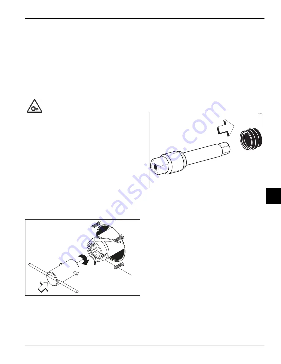
Note:

A dasher installation/removal tool is available 

to assist in the installation and removal of the dasher. 
To remove the dasher, insert the two short bars of the 
tool into the slots in the end of the dasher. Holding 
the long bar of the tool, turn the tool clockwise to lock 
the tool in the dasher, and then pull the dasher out.

Figure 6-19

Brush-Cleaning

1. Prepare a sink with an approved cleaning solution 

(examples: Kay-5® or Stera-Sheen®). 

Use warm 

water and follow the manufacturer’s 
specifications.

 If another approved cleaner is used, 

dilute it according to the label instructions. 
(

Important!

 Follow the label directions. Too 

strong


of a solution can cause parts damage, while too 

mild


of a solution will not provide adequate cleaning.

Make sure all brushes provided with the freezer are 
available for brush-cleaning.

2. Remove the seals from the driveshafts.

Figure 6-20

3. From the freezer door remove:

Front bearings

Handle arms

Plates

Stem  caps

Stem  screws

4. Remove all O-rings.

Note:

To remove O-rings, use a single-service towel 

to grasp the O-ring. Apply pressure upward until the 
O-ring pops out of its groove. With the other hand, 
push the top of the O-ring forward. It will roll out of the 
groove and can be easily removed. If there is more 
than one O-ring to be removed, always remove the 
rear O-ring first. This will allow the O-ring to slide 
over the forward rings without falling into the open 
grooves.

11381

Summary of Contents for C001

Page 1: ...OPERATOR S MANUAL Model C001 and C002 Custard Freezers 5 28 08 Original Publication Updated 8 18 2020 Original Operating Instructions 055073 M...

Page 2: ..._____________ Electrical Specs Voltage__________________ Cycle____________________ Phase____________________________________________ Maximum Fuse Size _________________________________________________...

Page 3: ...Assembly 4 5 Accessories 4 6 Section 5 User Interface C001 5 1 C002 5 2 Symbol Definitions 5 3 Section 6 Operating Procedures Assembly 6 1 Sanitizing 6 4 Priming for Continuous Run 6 4 Stopping a Cont...

Page 4: ...ii 055073 M Section 8 Troubleshooting Guide Section 9 Parts Replacement Schedule Section 10 Limited Warranty on Machines Section 11 Limited Warranty on Parts...

Page 5: ...e to follow this instruction may result in personal injury or death from electrical shock or hazardous moving parts as well as poor performance or damage to the machine WARNING This machine has many s...

Page 6: ...ention device is required on the incoming water connection side Please see the applicable national state and local codes for determining the proper configuration Water pressure to the unit must not ex...

Page 7: ...from abrasion If the supply cord is damaged it must be replaced by the manufacturer service agent or a similarly qualified person to avoid a hazard Secure supply cord ground lead to machine in a locat...

Page 8: ...e area immediately with cold water If burns are severe apply ice packs and contact a physician immediately NOTICE Taylor reminds technicians to be aware of and in compliance with local government laws...

Page 9: ...ur Taylor warranty is valid only if the parts are authorized Taylor parts purchased from the local authorized Taylor distributor and only if all required service work is provided by an authorized Tayl...

Page 10: ...is fact known to any technician he she employs It should also be noted that Taylor does not warrant the refrigerant used in its machines For example if the refrigerant is lost during the course of ord...

Page 11: ...installer The installation location is marked by the equipotential bonding symbol 5021 of IEC 60417 1 on the removable panel and the frame WARNING This machine must NOT be installed in an area where a...

Page 12: ...re very sharp and may cause injury CAUTION This machine must be placed on a level surface Failure to comply may result in personal injury or machine damage WARNING Only install this machine in a locat...

Page 13: ...ection 4 4 1 Models C001 and C002 Operator Parts Identification 4 Operator Parts Identification C001 Exploded View Figure 4 1 1 2 3 4 5 6a 6b 6c 6 8 22 10 21 11 9 12 11 13 14 15 16 17 18 19 20 6e 6d 7...

Page 14: ...062451 6c Pin Quick Release 3 16 X 1 S 027813 6d Tube Inner Regulator 059787 6e Regulator A Flow Outer 059784 7 Trim Rear Corner L 067971 8 Panel Rear 066551 9 Trim Rear Corner R 067972 10 Filter Air...

Page 15: ...OPERATOR PARTS IDENTIFICATION 4 3 Models C001 and C002 Operator Parts Identification 4 C002 Exploded View Figure 4 2 1 22 2 3 24 5a 5d 5b 5c 5e 6 4 1 7 8 23 18 9 10 11 12 13 14 15 16 17 21 19 20 5...

Page 16: ...or 059787 5e RegulatorA Flow Outer 059784 6 Panel Rear 053782 7 Panel Upper Side Right 054449 8 Pan Drip 11 5 8 Long 027503 9 Trim Rear Corner Right 054459 10 Panel A Side Right X66497 11 Nut 10 32 Wh...

Page 17: ...9 2 Arm Handle 055183 3 Plate Draw 054445 4 O ring 2 3 4 OD X 139W 70 055182 5 Screw Door Stem 055180 6 O ring 563 OD X 070W 013 043758 7 Bearing Front 013116 8 Blade Scraper 054485 Item Description P...

Page 18: ...riate Taylor approved food safe lubricant 1 2 4 3 5 6 7 8 Item Description Part No 1 Sanitizer Stera Sheen 055492 2 Lubricant Taylor 4 oz 047518 3 Kit A Tune Up X54630 1 4 Pail 10 Qt 013163 Item Descr...

Page 19: ...001 Figure 5 1 1 2 3 4 5 6 7 8 9 Item Description 1 Light Hopper Refrigeration 2 Switch HOPPER REFRIGERATION ON OFF 3 Light MIX LOW 4 Light Freeze Mode 5 Switch FREEZE CHILL Mode Item Description 6 Li...

Page 20: ...2 1 2 3 4 5 6 7 8 3 4 5 6 7 8 9 9 Item Description 1 Light Hopper Refrigeration 2 Switch HOPPER REFRIGERATION ON OFF 3 Light MIX LOW 4 Light Freeze Mode 5 Switch FREEZE CHILL Mode Item Description 6...

Page 21: ...arena the words on many of our operator switches and buttons have symbols to indicate their functions Your Taylor machine is designed with these international symbols The following chart identifies t...

Page 22: ...5 4 USER INTERFACE Models C001 and C002 User Interface 5 Notes...

Page 23: ...ing the freezer for the first time or need information to get to this starting point in our instructions turn to page 6 7 Disassembly and start there Assembly WARNING Make sure the power switch is in...

Page 24: ...d fit snugly but not so tightly that the dasher cannot be turned slightly to engage the driveshaft If the dasher slides in too easily with little or no resistance there will not be enough force agains...

Page 25: ...zer door Seat the door flush with the freezing cylinder With the door seated on the freezer studs install the stud nuts handscrews The short stud nuts go on the bottom and the long stud nuts go on top...

Page 26: ...HARGE OPENINGS Failure to do so may result in severe personal injury contaminated product or component damage Repeat these steps for the other side of the freezer Priming for Continuous Run 1 With san...

Page 27: ...Wait 1 or 2 minutes If the noise continues place the FREEZE CHILL switch in the OFF position until product begins flowing from the door Place the FREEZE CHILL switch back in the FREEZE mode position R...

Page 28: ...lid on the rerun container and place it in the walk in cooler Note If local health codes do not permit the use of rerun the product must be discarded Follow the instructions in the previous step exce...

Page 29: ...urn the tool clockwise to lock the tool in the dasher and then pull the dasher out Figure 6 19 Brush Cleaning 1 Prepare a sink with an approved cleaning solution examples Kay 5 or Stera Sheen Use warm...

Page 30: ...tion Brush clean the mix inlet holes in the mix hoppers Figure 6 22 8 Brush clean the rear shell bearings at the back of the freezing cylinders with the black bristle brush Figure 6 23 9 Thoroughly br...

Page 31: ...ush to clean the mix inlet hole which extends from the mix hopper down to the rear of the freezing cylinder Use the black bristle brush to thoroughly clean the rear shell bearing at the rear of the fr...

Page 32: ...er cooled check the water lines for kinks or leaks Kinks can occur when the machine is moved back and forth for cleaning or maintenance Deteriorated or cracked water lines should be replaced only by a...

Page 33: ...riveshaft seal a Replace worn nicked or missing driveshaft seal 6 1 b Inadequate lubrication b Lubricate properly 6 1 6 Product is not being fed into the freezing cylinder a Inadequate mix in hopper M...

Page 34: ...ing b Brush clean the rear shell bearing area regularly 6 7 15 Freezing cylinder walls are scored a The dasher assembly is damaged a Replace the dasher assembly 6 1 7 2 b The front bearing is either m...

Page 35: ...y 6 Months Annually Front Bearing X Inner Flow Regulator O rings X Draw Plate O ring X Freezer Door O ring X Driveshaft Seal X Scraper Blades X Black Bristle Brush 1 x 2 Inspect and replace if necessa...

Page 36: ...9 2 PARTS REPLACEMENT SCHEDULE Models C001 and C002 Parts Replacement Schedule 9 Notes...

Page 37: ...TED WARRANTY CONDITIONS 1 If the date of original installation of the Product cannot be verified then the limited warranty period begins ninety 90 days from the date of Product manufacture as indicate...

Page 38: ...epairs due to theft vandalism wind rain flood high water water lightning earthquake or any other natural disaster fire corrosive environments insect or rodent infestation or other casualty accident or...

Page 39: ...IAL OR INCIDENTAL DAMAGES INCLUDING CLAIMS FOR LOST SALES LOST PROFITS PRODUCT LOSS PROPERTY DAMAGES OR SERVICE EXPENSES ARE EXPRESSLY EXCLUDED THE EXPRESS WARRANTIES MADE IN THIS LIMITED WARRANTY MAY...

Page 40: ...10 4 LIMITED WARRANTY ON MACHINES Models C001 and C002 Limited Warranty on Machines 10 Notes...

Page 41: ...verified proof of purchase may be required at time of service 2 This limited warranty is valid only if the Part is installed and all required service work in connection with the Part is performed by a...

Page 42: ...warranty service work promptly upon arrival 9 Failure damage or repairs due to faulty installation misapplication abuse no or improper servicing unauthorized alteration or improper operation or use as...

Page 43: ...OR INCIDENTAL DAMAGES INCLUDING CLAIMS FOR LOST SALES LOST PROFITS PRODUCT LOSS PROPERTY DAMAGES OR SERVICE EXPENSES ARE EXPRESSLY EXCLUDED THE EXPRESS WARRANTIES MADE IN THIS LIMITED WARRANTY MAY NO...

Page 44: ...11 4 LIMITED WARRANTY ON PARTS Models C001 and C002 Limited Warranty on Parts 11 Notes...

Reviews: