2-2
CONTROLS
Model C152 & C161
Controls
2
Generation II Control Logic Board
The Generation II logic board's primary function is to
interpret modes of operation. The board monitors mix
levels and temperatures by sending commands to the
control's power board. Commands are sent via a ribbon
cable, enabling the proper relays on the power board to
open or close. See Figure 2-4.
Function
Interpret a mode of operation/monitor mix level and
temperature/monitor product viscosity or product
temperature and send a command to the power board
through a ribbon cable, enabling the proper relays on the
power board to be open or closed.
Logic Board Part Number
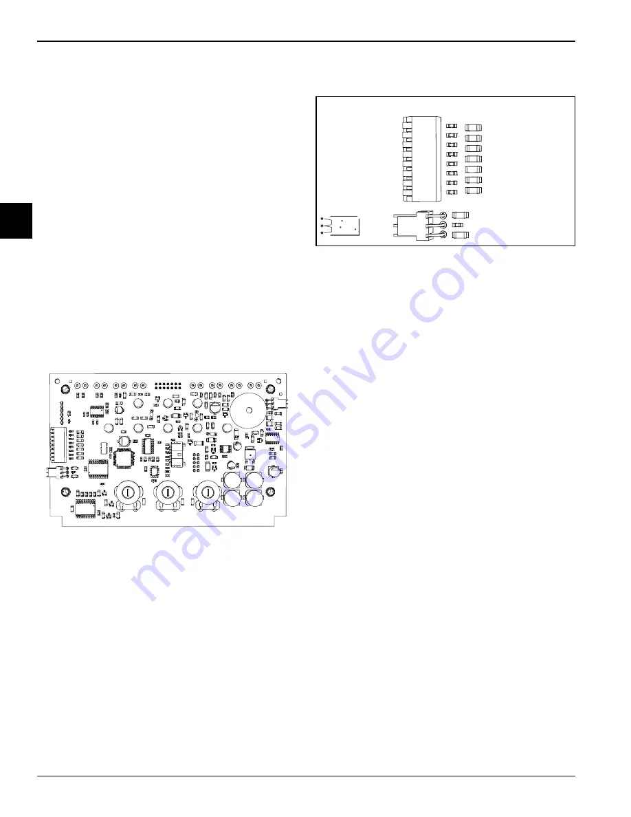
See Figure 2-1 for an illustration of the logic board (part
number X69571SER3).
Figure 2-1
Dip Switch and Jumpers
Dip switches and jumpers are located on the logic board,
see Figure 2-1. For descriptions of dip switches, See
Figure 2-2.
Figure 2-2
Power Board Part Number
See Figure 2-4 for an illustration of the power board (part
number X69574-SER).
Thermistor Probes
There are two types of thermistor probes used on these
freezers. The resistance value of the thermistor probes
corresponds with the temperature. As the temperature
increases, the probe resistance decreases.
Approximate Probe Resistance Readings
•
10,000 ohm at room temperature 77
º
F (25
º
C).
•
30,035 ohm at hopper temperature 35
º
F (2
º
C).
•
48,636 ohm at soft serve temperature
18
º
F (-7.7
º
C).
Viscosity Function
In soft-serve freezers, the logic board monitors draw
amperage on the beater motor, which is directly related to
the viscosity of the product in the freezing cylinder. When
the amp draw reaches its set point, the machine cycles
off. Therefore, the viscosity of the product will always be
consistent even though its temperature may vary slightly.
To monitor amperage, L1 power supplied to the beater
motor must pass through the power board beater
terminals. The same Softech
™
controls are used in both
X31602
-
Barrel Probe (senses temperature of
product in freezing cylinder)
X55540
-
Hopper Probe (senses temperature of
mix in hopper)
1
2
3
4
5
6
7
8
DIP SWITCH
UP = OFF
1-COMP 5
2-MIX LO CHIM
3-BTR 5
4-BTR 10
5-FAN 2
6-STBY DIS
7-INTERVAL
8-INTERVAL
SWITCH INTERVAL
7
8
TIME
OFF
OFF
OFF
OFF
ON
ON
ON
ON
16
14
11
5
MIX DIFF.
SHUNT
4.5
13
NO
JMPR
= 2
Summary of Contents for C152
Page 4: ...ii 085592 S Notes...
Page 30: ...2 12 CONTROLS Model C152 C161 Controls 2 Notes...
Page 36: ...3 6 TROUBLESHOOTING Model C152 C161 Troubleshooting 3 Notes...
Page 39: ...PARTS 4 3 Model C152 C161 Parts 4 Notes...
Page 56: ...4 20 PARTS Model C152 C161 Parts 4 Notes...
Page 88: ...6 10 WIRING DIAGRAMS Model C152 C161 Wiring Diagrams 6 Notes...


