CONTROLS
2-7
Model C152 & C161
Controls
2
Service Tips for Generation II Boards
Initial Service Tips
•
Use the clips under the channel to hold the DEC
plate when removed from the channel.
•
Check all connections.
•
Verify that the cable is secure.
•
Verify that all pins are securely fastened in their
sockets.
•
Verify that all cables correctly face away from the
boards. If the cable is attached incorrectly, damage
to the logic board will occur, and beater motor
operation will be disabled.
•
Verify probe resistance.
•
Use the self-test program.
Self-Test Program
The Generation II controls are programmed for a
self-test. The control can be used to help identify
problems in the power board, the logic board, and the
thermistor probes. The self-test program is not intended
to, and will not take the place of, a reasonable and
prudent service technician.
The self-test program is divided into two sections. The
first section is performed automatically by the logic
board, and the second section is performed by the
technician.
This test is designed to aid in identifying problems within
the logic board, the power board, or the thermistor
probes.
Self-Test—Part I
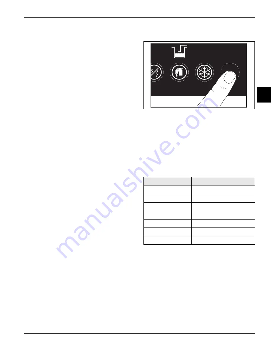
The self-test program is initiated by holding down the
Pump button on the logic board while simultaneously
turning on the power switch. The Pump button may or
may not be visible. Hold down the button until all of the
buttons illuminate.
Note:
If all of the buttons do not illuminate, or if the test
cannot be initiated, the logic board is damaged.
Figure 2-3
Each illuminated button corresponds with a particular
relay. The illuminated button on the panel does not
extinguish until the test is completed for that particular
relay.
Note:
Each relay closes for 3 seconds during this test.
As the relay opens, the corresponding light extinguishes.
There is a 10-second pause between each relay’s
activation.
Table 2-2
When the self-test is initiated, all buttons remain on for
3 seconds. At this time, the processor begins to check
the power board relays as follows:
The Set Point light turns off.
Ten seconds after the Set Point light turns off:
1. The Mix relay closes and opens again. The
Mix-Low light extinguishes.
2. The Fan relay closes and opens again. The
Mix-Out light extinguishes.
3. The Pump relay closes and opens again. The Mix
light extinguishes.
Logic Board Light
Corresponding Relay
MIX LOW
Mix Relay
MIX OUT
Fan Relay
MIX
Pump Relay
STANDBY
Beater Motor Relay
WASH
Compressor Relay
AUTO
Spinner Relay
PUMP
Portion Relay
131560
Summary of Contents for C152
Page 4: ...ii 085592 S Notes...
Page 30: ...2 12 CONTROLS Model C152 C161 Controls 2 Notes...
Page 36: ...3 6 TROUBLESHOOTING Model C152 C161 Troubleshooting 3 Notes...
Page 39: ...PARTS 4 3 Model C152 C161 Parts 4 Notes...
Page 56: ...4 20 PARTS Model C152 C161 Parts 4 Notes...
Page 88: ...6 10 WIRING DIAGRAMS Model C152 C161 Wiring Diagrams 6 Notes...


