6-4
OPERATING PROCEDURES
Model C300
Operating Procedures
6
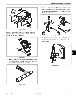
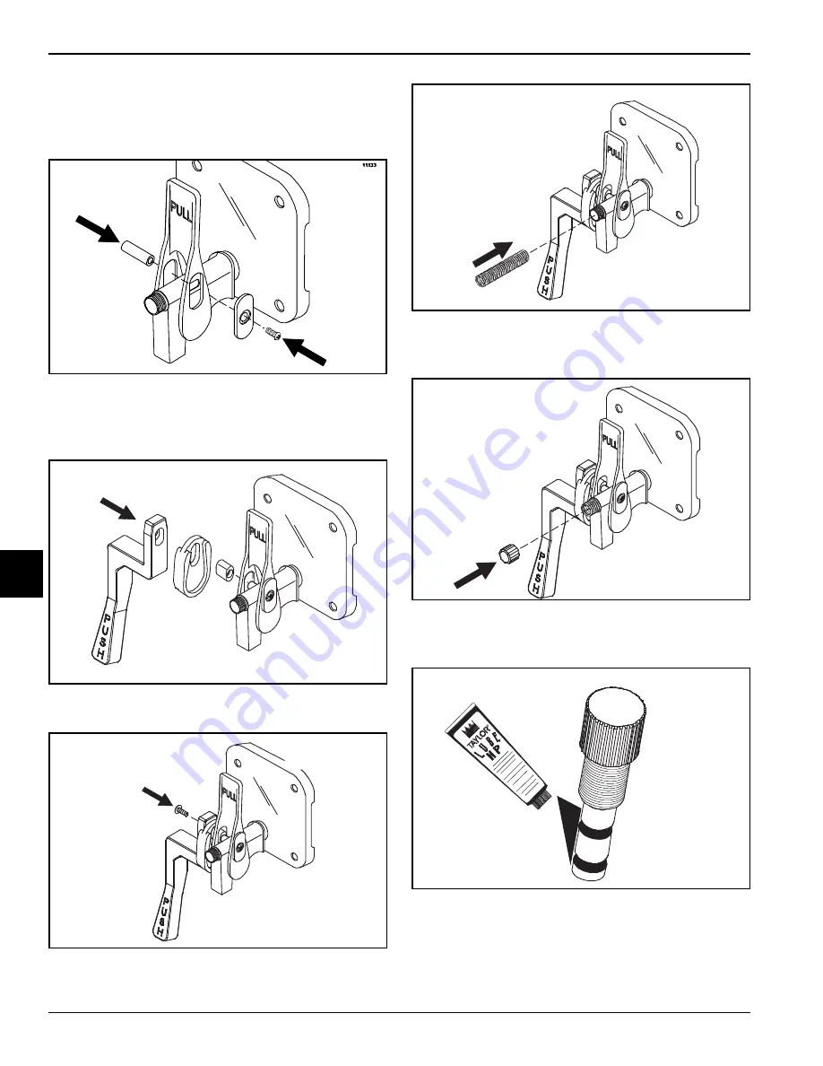
10. Slide the pivot pin through the draw handle and into
the draw valve. Place the draw handle slide over the
opening in the draw handle and the pivot pin. Secure
the assembly with the screw.
Figure 6-11
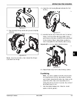
11. Install the handle pin through the mounting adaptor
and into the ADA handle. Mount the assembled ADA
handle onto the pivot pin.
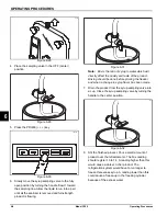
Figure 6-12
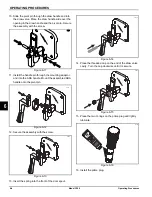
12. Secure the assembly with the screw.
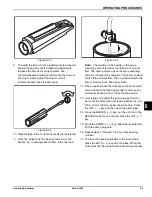
Figure 6-13
13. Insert the spring into the front of the door spout.
Figure 6-14
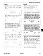
14. Place the threaded cap on the end of the draw valve
cavity. Turn the cap clockwise until it is secure.
Figure 6-15
15. Place the two O-rings on the prime plug and lightly
lubricate.
Figure 6-16
16. Install the prime plug.
11501
11445
11446
11447
11193
Summary of Contents for C300 NP
Page 14: ...3 4 SAFETY Model C300 Safety 3 Notes...
Page 18: ...4 4 OPERATOR PARTS IDENTIFICATION Model C300 Operator Parts Identification 4 Notes...
Page 26: ...5 8 USER INTERFACE Model C300 User Interface 5 Notes...
Page 40: ...6 14 OPERATING PROCEDURES Model C300 Operating Procedures 6 Notes...
Page 42: ...7 2 OPERATOR CHECKLIST Model C300 Operator Checklist 7 Notes...
Page 46: ...9 2 Model C300 Parts Replacement Schedule PARTS REPLACEMENT SCHEDULE 9 Notes...
Page 52: ...LIMITED WARRANTY ON PARTS 11 4 Model C300 Limited Warranty on Parts 11 Notes...

