6-4
OPERATING PROCEDURES
Model C612
Operating Procedures
6
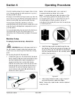
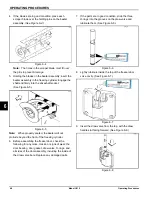
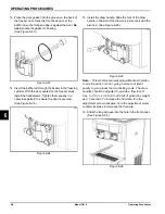
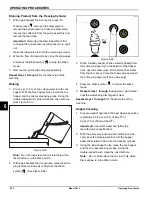
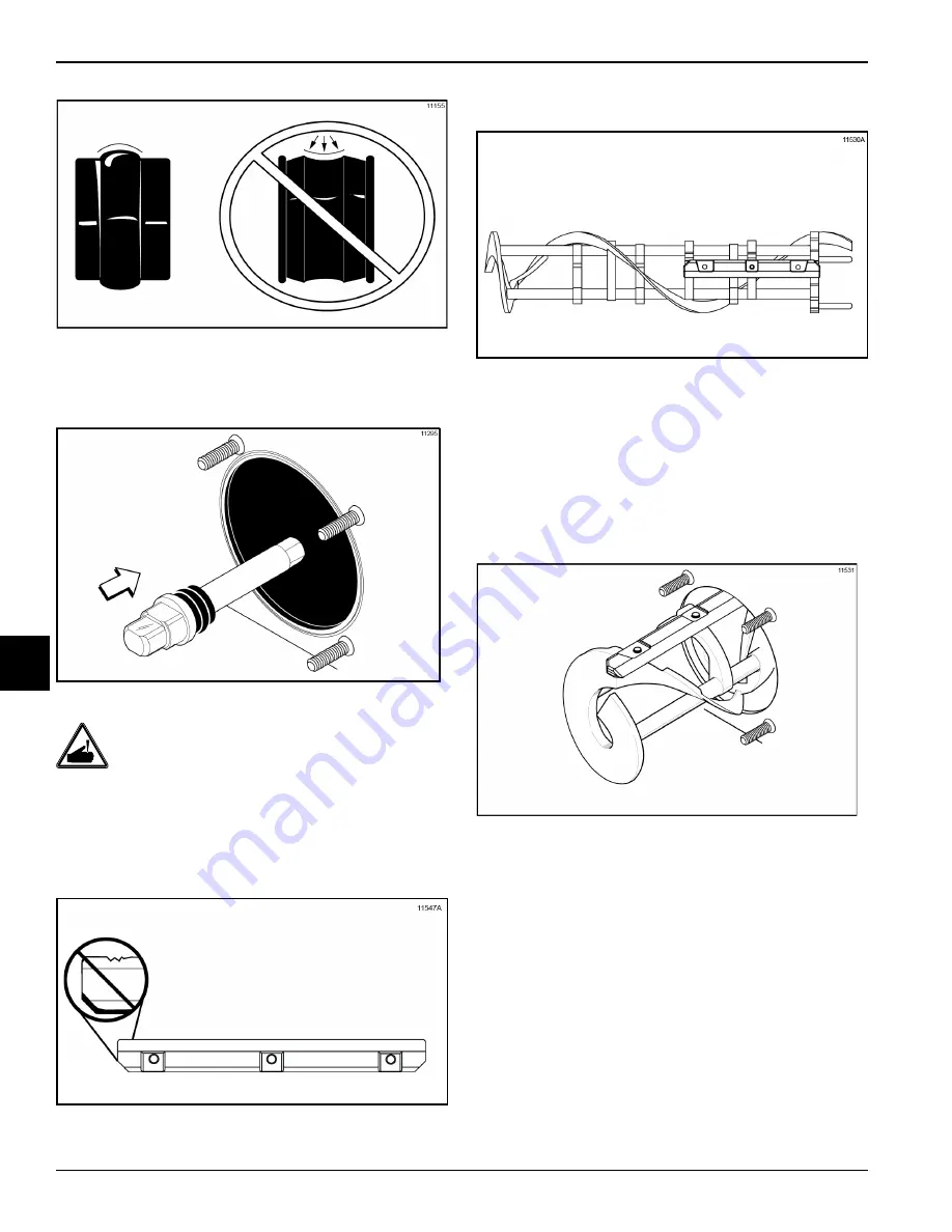
Figure 6-13
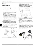
2. Insert the beater driveshaft through the rear shell
bearing in the freezing cylinder and engage the hex
end firmly into the drive coupling. (See Figure 6-14.)
Figure 6-14
WARNING!
Use extreme caution
when
handling the beater assembly.
The scraper blades are
very sharp and may cause injury.
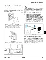
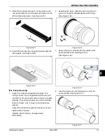
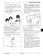
3. Before installing the beater assembly, inspect the
scraper blades for any signs of wear or damage. If a
scraper blade is nicked or worn, replace both blades.
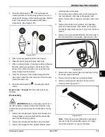
Figure 6-15
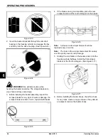
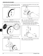
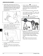
4. If the blades are in good condition, place the rear
scraper blade over the rear holding pin on the beater.
Figure 6-16
Note:
Soft serve side scraper blades should be
replaced every 3 months.
Note:
The hole on the scraper blade must fit securely
over the pin to prevent costly damage.
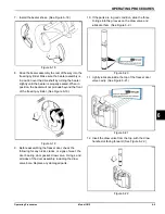
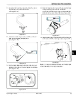
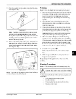
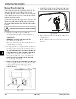
5. Holding the rear blade on the beater, slide it into the
freezing cylinder halfway. Install the front scraper
blade over the front holding pin. (See Figure 6-17.)
Figure 6-17
6. Before installing the beater shoes, check the shoes
for any nicks, cracks, or signs of wear. If any defects
are present, replace the beater shoes.
Summary of Contents for C612
Page 8: ...1 4 TO THE INSTALLER Model C612 To the Installer 1 Notes...
Page 54: ...9 2 PARTS REPLACEMENT SCHEDULE Model C612 Parts Replacement Schedule 9 Notes...
Page 58: ...10 4 LIMITED WARRANTY ON EQUIPMENT Model C612 Limited Warranty on Equipment 10 Notes...
Page 62: ...11 4 LIMITED WARRANTY ON PARTS Model C612 Limited Warranty on Parts 11 Notes...

