Section 6
6-1
Model C612
Operating Procedures
6
Operating Procedures
The C612 machine stores mix in a hopper. It has a 3.4 qt.
(3.2 L) freezing cylinder for soft serve and a 7 qt. (6.6 L)
freezing cylinder for shake.
We begin our instructions at the point when we enter the
store in the morning and find the parts disassembled and
laid out to air-dry from the previous night's cleaning.
These opening procedures will show you how to
assemble these parts into the freezer, sanitize them, and
prime the freezer with
fresh
mix in preparation to serve
your first portion.
If you are disassembling the machine for the first time or
need information to get to this starting point in our
instructions, turn to Disassembly on page 6-15 and start
there.
Machine Setup
Freezing Cylinder Assembly—Shake Side
WARNING!
Make sure the power switch is in
the OFF position. Failure to follow this instruction may
result in severe personal injury from hazardous moving
parts.
Set up using the parts for the shake side.
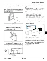
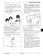
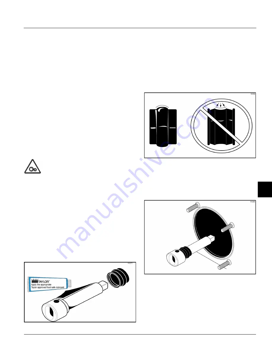
1. Lubricate the groove on the shake beater driveshaft
before installing. Slide the beater driveshaft boot seal
over the small end of the beater driveshaft and
engage it into the groove on the shaft. Heavily
lubricate the inside portion of the boot seal and also
lubricate the flat end of the boot seal that comes in
contact with the rear shell bearing. Apply an even
coat of lubricant to the shaft.
Do not
lubricate the
square end. (See Figure 6-1.)
Figure 6-1
Note:
When lubricating parts, use an approved
food-grade lubricant (example: Taylor Lube).
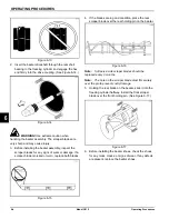
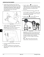
Note:
To ensure that the mix does not leak out of the
back of the freezing cylinder, the middle section of the
boot seal should be convex, or extend from the seal. If
the middle section of the boot seal is concave, or
extending into the middle of the seal, turn the seal inside
out. (
See Figure 6-2
.)
Figure 6-2
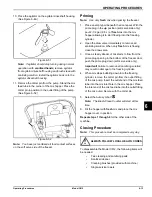
2. Install the shake beater driveshaft through the rear
shell bearing in the freezing cylinder and engage the
square end firmly into the driveshaft coupling. Make
sure the driveshaft fits into the drive coupling without
binding. (See Figure 6-3.)
Figure 6-3
3. Check scraper blades for nicks or signs of wear. If
any nicks are present, replace the blades.
Note:
Shake side scraper blades should be replaced
every 6 months.
Summary of Contents for C612
Page 8: ...1 4 TO THE INSTALLER Model C612 To the Installer 1 Notes...
Page 54: ...9 2 PARTS REPLACEMENT SCHEDULE Model C612 Parts Replacement Schedule 9 Notes...
Page 58: ...10 4 LIMITED WARRANTY ON EQUIPMENT Model C612 Limited Warranty on Equipment 10 Notes...
Page 62: ...11 4 LIMITED WARRANTY ON PARTS Model C612 Limited Warranty on Parts 11 Notes...

