OPERATING PROCEDURES
6-15
Model C612
Operating Procedures
6
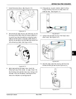
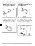
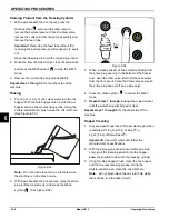
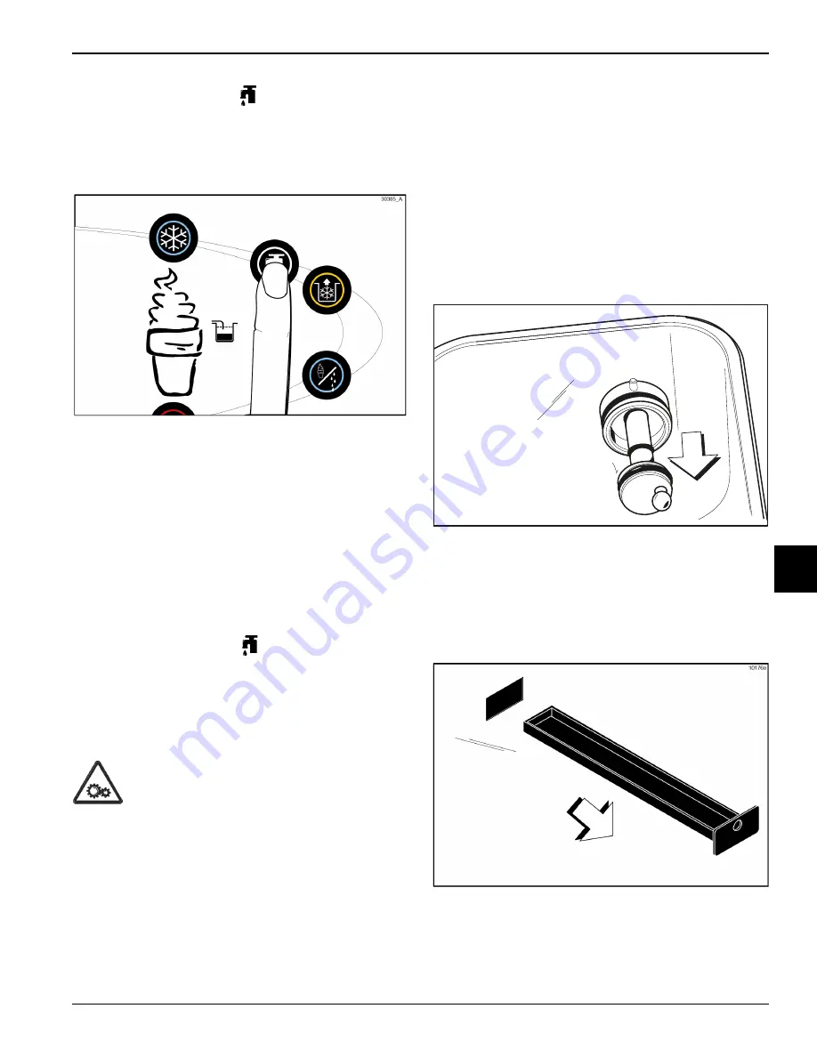
4. Press the Wash symbol
. This will cause the
cleaning solution in the freezing cylinder to come in
contact with all areas of the freezing cylinder. Wait at
least 5 minutes before proceeding with these
instructions. (See Figure 6-55.)
Figure 6-55
5. Place an empty pail beneath the door spout.
6. Raise the prime plug (soft serve side only).
7. When a steady stream of cleaning solution is flowing
from the prime plug opening in the bottom of the
freezer door (soft serve side only), open the draw
valve. Draw off all the solution.
8. Once the cleaning solution stops flowing from the
door spout, close the draw valve and the prime plug
(soft serve side only).
9. Press the Wash symbol
, canceling the Wash
mode.
Repeat steps 1 through 9
for the other side of the
machine.
Disassembly
WARNING!
Make sure the power switch is in
the OFF position. Failure to follow this instruction may
result in severe personal injury from hazardous moving
parts.
1. Remove the handscrews, freezer door, beater and
scraper blades, and driveshaft with the driveshaft
seal from the freezing cylinder.
2. Remove the driveshaft seal from each driveshaft.
3. Remove the hopper covers, agitator blades, pump
retaining clips, and pumps.
4. From each pump cylinder, remove the retaining pin,
mix inlet adaptor, valve cap, pump gasket, and
piston. Remove the O-ring from the piston and valve
cap.
5. Remove the freezer door gaskets, front bearings,
pivot pin, draw handles, draw valves, prime plugs,
and design caps. Remove the O-rings from the draw
valves.
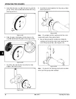
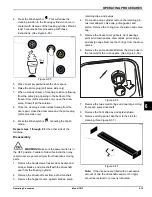
6. Remove the pump driveshafts from the drive hubs in
the rear wall of the mix hoppers. (See Figure 6-56.)
Figure 6-56
7. Remove the two small O-rings and one large O-ring
from each pump driveshaft.
8. Remove the front drip tray and splash shield.
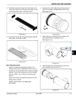
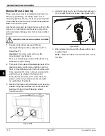
9. Remove all drip pans. Take them to the sink for
cleaning. (See Figure 6-57.)
Figure 6-57
Note:
If the drip pans are filled with an excessive
amount of mix, the driveshaft seal(s) or O-ring(s)
should be replaced or properly lubricated.
12002
Summary of Contents for C612
Page 8: ...1 4 TO THE INSTALLER Model C612 To the Installer 1 Notes...
Page 54: ...9 2 PARTS REPLACEMENT SCHEDULE Model C612 Parts Replacement Schedule 9 Notes...
Page 58: ...10 4 LIMITED WARRANTY ON EQUIPMENT Model C612 Limited Warranty on Equipment 10 Notes...
Page 62: ...11 4 LIMITED WARRANTY ON PARTS Model C612 Limited Warranty on Parts 11 Notes...

